- support@ddgear.com
- North 3F, Building 13-2, Zhixin Park, NO.1099 Xianhua South Street, Wucheng, Jinhua, Zhejiang, China.
Products


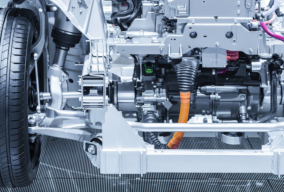
Drive Motor Shaft – High Precision Shaft for EV | DD Gear
Product Details
FAQ
Features & Benefits
-
Supports rotor and delivers torque to the drivetrain
The drive motor shaft runs through the rotor, carries the laminated core or magnet assembly, and transmits mechanical power from the motor to the reduction gearset or coupling. -
Engineered for high-speed EV operation
EV traction motors often operate with base speeds above 10,000 rpm and maximum speeds exceeding 20,000 rpm; some designs reach above 50,000 rpm. Shaft straightness, runout, and dynamic balance are tightly controlled to reduce vibration and bearing loads at these speeds. -
High strength with optimized weight
Rotor shafts in traction motors must carry high torque while remaining as light as possible; induction-hardened zones on seats and splines allow local strength without unnecessary mass. -
Material and heat treatment tuned to duty cycle
Carbon and alloy steels are commonly used for motor shafts because of their strength-to-weight ratio; stainless steels may be selected where corrosion or temperature demands it. DD Gear defines quench-and-temper or induction hardening windows according to torque, speed, and life requirements of each EV program. -
Integration with assembled rotor designs
Modern traction motors often use assembled rotor shafts, where laminations, sleeves, magnets, and shaft are joined using interference fits, welding, or other technologies. DD Gear can machine the shaft features and interfaces that support these designs and maintain concentricity and stiffness. -
Interfaces for gears, couplings, and cooling concepts
The drive motor shaft can include splines, keyways, or other interfaces for the primary reduction gear, as well as features that interface with rotor cooling concepts or seals used in oil-cooled drive units. -
From prototypes to series production
We support prototype batches for motor development and dyno testing, followed by stable series production with controlled processes, inspection plans, and documentation aligned with automotive requirements.
Technical Specifications
Final data will be defined according to the customer’s drawing and EV duty cycle.
| Item | Typical Option |
| Gear Type | Shaft |
| Material | Carbon and alloy steels suitable for high-speed motor shafts (e.g. 40Cr, 42CrMo equivalents, other automotive-grade shaft steels) |
| Heat Treatment |
Quench-and-temper, induction hardening on seats/splines, local hardening in 1–3 zones as required |
| Surface Hardness | Typically 50–60 HRC or per drawing |
| Accuracy | Automotive-grade accuracy per ISO 1328 / DIN / AGMA |
Applications
-
Traction motors in front- or rear-wheel-drive EVs
Drive motor shafts carrying rotor stacks for central or offset motors that feed single-speed or multi-speed gearboxes. -
Integrated e-axles and drive units
Rotor shafts within compact e-axles where motor, inverter, and reduction gearset are packaged in one housing, requiring careful attention to shaft length, stiffness, and cooling interfaces. -
High-speed motors for performance EVs
Drive motor shafts designed for motors with very high base and maximum speeds, where shaft dynamics and balancing become critical to reliability and NVH. -
Hybrid and range-extender generators
Rotor shafts in hybrid traction motors or generator units, where the shaft must support both motor and generator modes with varying torque and speed profiles.
Gear Manufacturing Process
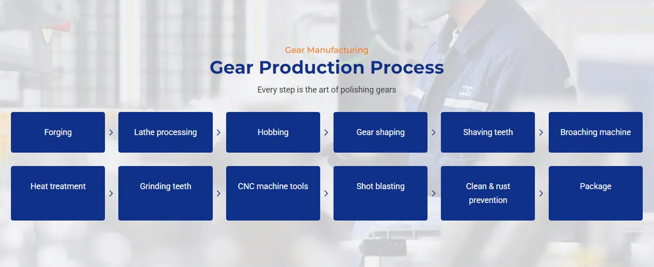
Every drive motor shaft is produced under a controlled manufacturing route designed for precision and durability. A typical process flow is:
-
Forging or bar cutting of shaft blanks
-
Lathe machining of diameters, bearing journals, and reference surfaces
-
Milling, drilling, and spline or keyway machining
-
Additional CNC machining as required by geometry
-
Heat treatment (such as quenching and tempering, induction hardening)
-
Shot blasting and stress relief as required
-
Finish machining and grinding of critical mounting surfaces and journals
-
Cleaning and rust prevention treatment
-
Final inspection and packaging for shipment
Precision Gear Customization Process
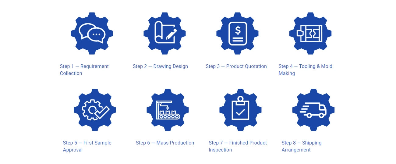
To support custom drive motor shaft projects, DD Gear follows a clear, eight-step customization process:
Step 1 – Requirement Collection
Customers provide design requirements, 2D drawings, 3D models, or physical samples, together with basic duty cycle information (torque, speed, life, installation).
Step 2 – Drawing Design & Optimization
Based on the provided drawings or samples, DD Gear prepares or optimizes detailed manufacturing drawings and shares them with the customer for confirmation.
Step 3 – Quotation
After the drawings and technical points are confirmed, we issue a precise quotation covering tooling, piece price, lead time, and quality requirements.
Step 4 – Tooling & Fixture Preparation
Once the price is confirmed, we arrange tooling and fixture production. Any tooling cost is agreed with the customer in advance and can be offset or refunded after mass orders, according to the commercial agreement.
Step 5 – First Sample Approval
After tooling and fixtures are ready, we manufacture the first sample batch—typically within about 30 days—and ship it to the customer for testing.The customer inspects and validates the samples in their gearbox or test bench and provides feedback on dimensions, performance, and any required adjustments.
Step 6 – Mass Production
When the sample is approved, we start mass production according to the agreed production plan and quality standards.
Step 7 – Finished Product Inspection
After production, we inspect hardness, dimensions, runout, tooth accuracy, and other critical characteristics to ensure full compliance with the drawing and standards.
Step 8 – Shipping Arrangement
Once inspection is passed and shipment is approved by the customer, we arrange booking, packaging, and delivery to the specified destination.
Quality Assurance & Inspection
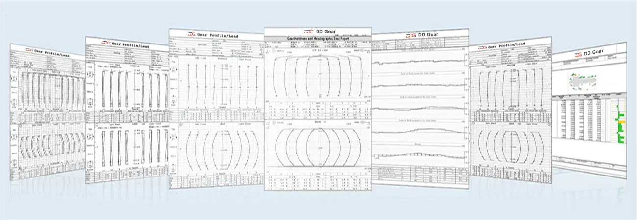
DD Gear applies the same quality philosophy to all precision gears:
-
Quality management systems based on ISO 9001 and IATF 16949
-
Process control from incoming material to final inspection, including:
-
Material certification and chemical composition checks
-
Hardness and case depth verification after heat treatment
-
Gear measurement for profile, lead, pitch, and runout
-
Surface roughness testing on gear flanks and journals
-
Dimensional inspection with calibrated gauges and CMMs
-
-
Traceability for each batch with inspection records and reports
- Optional documentation such as PPAP/FAIR packs on request
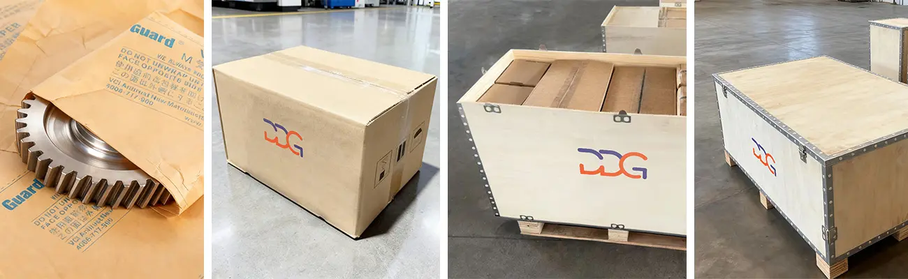
Packaging
Usage & Installation Notes
-
Ensure proper fit between drive motor shaft and rotor stack, laminations, or sleeves, following assembly procedures to avoid residual stresses or misalignment.
-
Verify that bearing selection and journal tolerances match the shaft design and operating speeds; improper fits can increase friction and reduce bearing life.
-
Use specified torque and sequence for any shaft nuts, flanges, or couplings to maintain alignment and prevent loosening.
-
During motor assembly, protect shaft surfaces from nicks and scratches, especially on bearing seats and sealing areas.
-
Observe limits for torque, speed, and temperature defined for the motor and shaft; exceeding them can accelerate fatigue and wear.
-
During maintenance, inspect splines, keyways, and bearing journals for wear, fretting, or corrosion, particularly in oil-cooled or high-humidity environments.
-
Store finished shafts in dry, clean conditions with anti-rust protection and avoid impact on critical surfaces.
Company Strength – DD Gear
-
Specialized in small module, high-precision gears and shafts for EVs, humanoid robots, AGVs, and intelligent automation.
-
Integrated manufacturing from forging and machining to heat treatment and gear grinding.
-
Quality systems aligned with automotive standards, with experience supporting OEM and Tier 1 projects.
-
Engineering support covering concept feasibility, DFM reviews, and failure analysis feedback.
-
Global export capability with experience serving customers in multiple countries.
Q1: What information do you need for a drive motor shaft quotation?
We normally need 2D drawings (PDF), 3D models (STEP/IGES if available), material and heat treatment requirements, expected annual volume, and basic application data such as motor type, torque-speed curve, and life targets.
Q2: Can you help with shaft design for high-speed motors?
Yes. Our engineering team can review your shaft layout and boundary conditions and provide suggestions on shaft diameter, fillet radii, bearing journal design, and induction hardening zones to help meet critical speed, fatigue, and NVH requirements.
Q3: What lead time should we expect for prototypes and production?
Prototype drive motor shafts are usually available in around 2–3 weeks after final drawing confirmation and tooling readiness. Mass production lead time depends on quantity and process route and will be confirmed during quotation.
Q4: Do you supply the complete rotor assembly or only the shaft?
DD Gear primarily supplies the machined and heat-treated shaft; rotor lamination stacks, sleeves, magnets, and balancing weights are usually assembled by the motor manufacturer. On request, we can discuss extended scope together with your engineering team.
Q5: What materials and heat treatments can you provide?
We work with a range of carbon and alloy steels suitable for high-speed shafts, combined with quench-and-temper or induction hardening in selected zones to provide local wear resistance and overall toughness.
Q6: What is your typical MOQ for drive motor shafts?
MOQ depends on part complexity and tooling. We support flexible MOQ for development and pilot builds, then align batch sizes with your series production plan.
Q7: Can you provide inspection and balancing reports with each batch?
Yes. Dimensional inspection reports, hardness records, and, where required, rotor shaft balancing data can be provided according to your documentation needs.
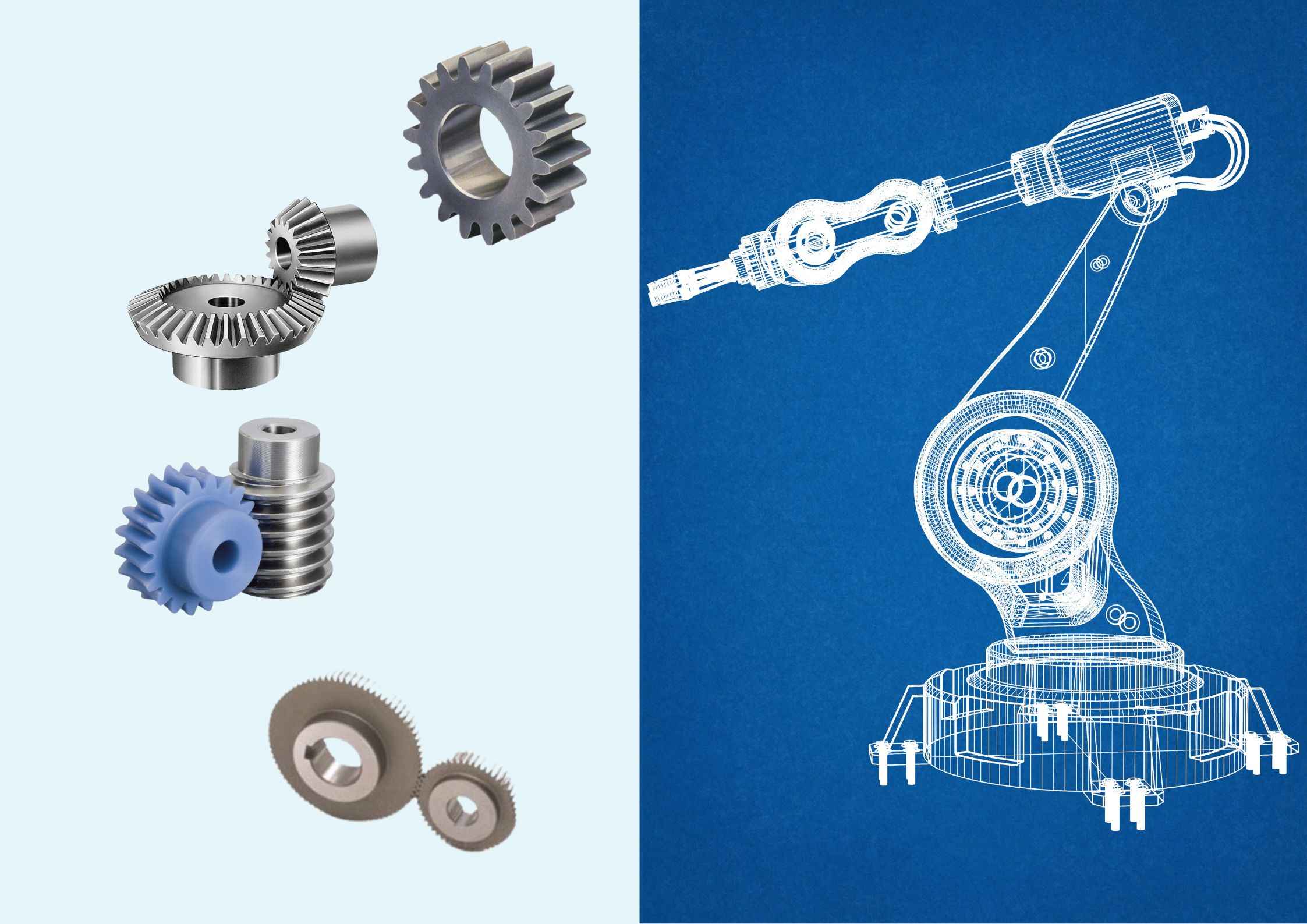
Reliable precision gears for robotics, automotive, and beyond.
Custom Gears for Sliding, Swing & Industrial Doors | DD Gear
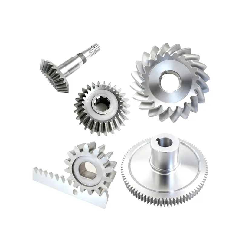
Automatic Door Gear from DD Gear is a range of custom-designed, small- to medium-module gears and shafts used in automatic sliding doors, swing doors, revolving doors and industrial doors (sectional, rolling, high-speed doors). In these systems, compact electric motors drive gearboxes and gear trains that must deliver high starting torque, smooth motion and very low noise while opening and closing heavy door leaves hundreds or thousands of times per day. Typical automatic door operators use one or more stages of spur and helical gears in combination with worm gears or bevel gears. Spur gears provide simple, efficient torque transfer for intermediate stages. Helical gears, with their angled teeth and higher contact ratio, help achieve quieter and smoother running, which is critical in hotels, hospitals, offices and residential buildings. Worm gears are often used for high reduction ratios and self-locking behavior, improving safety when the door is at rest and reducing backdrive from wind loads or manual pushing. In some operators, bevel gears change shaft direction between the motor, transmission and drive shaft or belt/chain. DD Gear manufactures Automatic Door Gears strictly on a custom, build-to-print basis. Using customer drawings or validated samples, we supply spur and helical pinions and gears, worm gears and worm wheels, bevel gears, gear shafts and related components for door operators. Through appropriate alloy steels, surface treatments, controlled heat treatment and precision machining, DD Gear helps door-operator OEMs and system integrators build drives that provide quiet operation, long life and reliable performance in entrances exposed to dust, temperature changes and frequent cycling.
Custom Precision Gears for Electric Wheelchair | DD Gear
Electric Wheelchair Gear from DD Gear covers a family of small-module, custom-designed gears and shafts used in electric wheelchairs, powered mobility scooters and related assistive devices. In these products, compact electric motors drive wheel-side or centrally mounted gearboxes that must deliver high torque at very low vehicle speed, provide smooth, gentle acceleration and braking, and work reliably for years in both indoor and outdoor environments. Typical electric wheelchairs use a single-speed reduction between the high-speed motor and the drive wheel. This reduction is often realized by a worm gear stage, a spur/helical reduction stage, or a planetary gear set integrated into a wheel-side gearbox. Worm gears are commonly used because they can offer high reduction ratios and inherent self-locking behavior in many designs, helping the chair hold position on slopes when the motor is not powered. Spur and helical gears are used in intermediate stages or in designs where efficiency and low noise are prioritized. Planetary gear trains may be used when high torque density and compact packaging are critical, especially in wheel modules. DD Gear manufactures Electric Wheelchair Gears strictly on a custom, build-to-print basis. Based on customer drawings or validated samples, we supply worm gears and worm wheels, spur and helical gears, planetary gear components (sun, planet, ring), gear shafts and wheel-drive gear elements. Using case-hardening steels, controlled heat treatment and small-module precision machining or grinding, DD Gear helps mobility OEMs and system suppliers design drivetrains that offer quiet operation, safe holding behavior, good efficiency and long service life, enhancing comfort and confidence for end users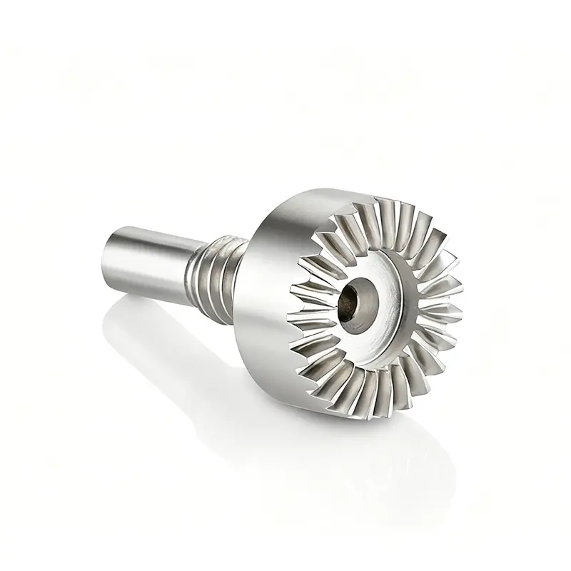
Custom Precision Gears for Surgical Robotics | DD Gear
Surgical Robot Gear from DD Gear covers a family of small-module, high-precision gears and shafts used in surgical robots, robotic-assisted surgical systems and related medical robotic platforms. In these applications, compact actuators drive robotic arms, wrists, end effectors and instrument modules that must deliver micron-level positioning, smooth motion and highly repeatable force control, often in minimally invasive procedures around critical anatomy. To achieve this, surgical robots commonly use spur and helical gears, planetary gear sets and gears integrated with harmonic or other precision reducers inside joint and instrument actuators. These gear stages must work with high-resolution encoders and advanced control algorithms, providing low backlash, high torsional stiffness and consistent friction characteristics across the full range of motion. At the same time, many components operate near the sterile field and must tolerate frequent cleaning and sterilization cycles, use biocompatible or low-outgassing materials and lubricants, and minimize particle generation. DD Gear manufactures Surgical Robot Gears strictly on a custom, build-to-print basis. Based on your drawings or validated samples, we supply spur, helical and bevel gears, planetary components (sun/planet/ring), gear shafts, small-module pinions and interface gears for precision reducers, using carefully selected alloy steels, stainless steels and, where specified, non-magnetic or corrosion-resistant materials. With controlled heat treatment, precision machining and (when required) ground tooth flanks, DD Gear supports surgical robot OEMs and system suppliers in building actuators that deliver precise, smooth and reliable motion, while supporting cleaning and sterilization concepts defined at the system level.
Custom Precision Gears for Automated Guided Vehicles | DD Gear
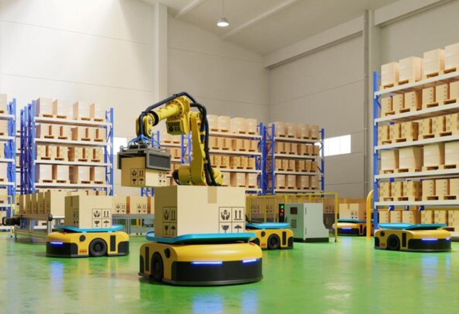
AGV Gear from DD Gear refers to a range of custom, small-module gears and shafts specifically engineered for Automated Guided Vehicles (AGV) and Autonomous Mobile Robots (AMR) used in warehouses, factories, distribution centers and logistics hubs. In these applications, compact electric motors drive wheel-mounted or centrally mounted gearboxes that must deliver high torque at low travel speed, provide smooth, precise motion control, and withstand continuous start/stop cycles in 24/7 intralogistics operations. Typical AGV drivetrains combine motor + reduction gearbox + drive wheel, often in a wheel hub or wheel-side gearbox design, while steering and lifting functions may use additional gear stages or screw drives. Single- or multi-stage spur and helical gears are common in wheel drives and intermediate stages, while planetary gear sets are widely used where high torque density and compact packaging are required, such as in drive wheels for heavy loads or AGV forklifts. In some architectures, gears are also combined with chain or belt stages to reach the final wheel or mast. Compared with traditional industrial vehicles, AGV/AMR systems place greater emphasis on low noise, smooth operation, positioning accuracy and long maintenance intervals. DD Gear manufactures AGV gears strictly on a custom, build-to-print basis, supplying spur and helical gears, planetary gear components (sun/planet/ring), bevel gears, gear shafts and wheel-drive gear elements based on customer drawings or validated samples. Using case-hardening steels, controlled heat treatment and small-module precision machining or grinding, DD Gear supports AGV and AMR OEMs in building transmissions that provide high efficiency, compact size, low NVH and long service life in demanding indoor and outdoor logistics environments.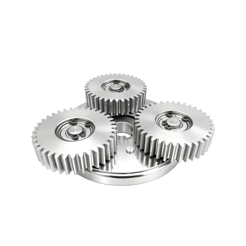
Custom Reduction Gears & Shafts for E-Motorcycle | DD Gear
E-Motorcycle Gear from DD Gear refers to a range of small-module reduction gears and shafts engineered for electric motorcycles, e-scooters, e-mopeds and high-power e-bikes. Instead of multi-speed gearboxes like those used in traditional ICE motorcycles, most electric two-wheelers use a single-speed reduction between the high-speed electric motor and the wheel. This reduction can be realized by hub-motor planetary gear sets, mid-drive spur/helical gear stages, or a combination of gear reduction + chain or belt drive. In hub-motor architectures, a compact planetary gear train is often integrated inside the wheel hub to reduce motor speed and increase wheel torque while keeping unsprung mass and noise under control. In mid-drive or centrally mounted motor layouts, the motor drives an intermediate shaft via spur or helical gears, and torque is then transferred to the rear wheel by a chain or belt. In both cases, the gears must handle high input speeds, frequent acceleration/deceleration, high torque at low road speed, outdoor exposure and strict NVH requirements, all within tight packaging envelopes. DD Gear manufactures E-Motorcycle Gears strictly on a custom, build-to-print basis. Using customer drawings or validated samples, we supply spur and helical pinions and gears, planetary gears (sun/planet/ring), gear shafts and hub-motor gear components. With appropriate case-hardening steels, controlled heat treatment and small-module precision machining or grinding, DD Gear helps electric two-wheeler OEMs and system suppliers build drivetrains that deliver high efficiency, quiet operation, compact packaging and long service life, supporting both urban commuting and higher-performance applications
Custom Precision Gears for Packaging Machinery | DD Gear
Packaging Machinery Gear from DD Gear is a family of small- to medium-module, custom-designed gears used in form-fill-seal (FFS) machines, cartoners, case packers, palletizers, labelers and conveyor systems. In modern packaging lines, gears are responsible for coordinating motion between film feed, sealing jaws, product infeed, carton erection, filling, closing and outfeed. They must operate at high speed, often in 24/7 duty, while maintaining precise timing and position to avoid film waste, misaligned seals, product jams and unplanned downtime. Most packaging mechanisms rely on spur and helical gears in gearboxes and timing stages for parallel shafts. Spur gears provide simple, highly efficient torque transmission and are widely used in indexing, feed and cam drives. Helical gears, with their angled teeth and higher contact ratio, offer smoother, quieter running and higher load capacity, which is important in high-speed packaging halls where noise and vibration affect both productivity and operator comfort. In right-angle or compact layouts, bevel gears, worm gears or planetary sets may be used to change direction or achieve higher reduction ratios in a limited envelope. DD Gear manufactures Packaging Machinery Gears strictly on a custom, build-to-print basis. Based on your drawings or validated samples, we supply precision spur, helical, bevel gears, gear shafts and internal gears, using case-hardening steels, nitriding steels, stainless or corrosion-resistant grades, and selected engineering plastics where appropriate. Through controlled heat treatment, finishing and systematic quality control, we help packaging OEMs and retrofitters build gear trains that deliver stable speed ratios, smooth motion, low noise and long service life, even in demanding environments involving dust, humidity or washdownExploring The Science of Precision Gears
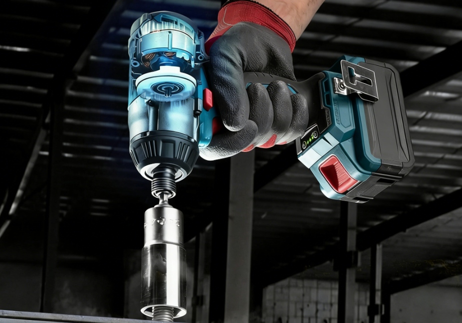
Brushless Power Tool Gears: Maximize Torque & Efficiency
In the world of professional construction and industrial assembly, the transition to brushless motor technology has fundamentally changed expectations for performance. A modern cordless drill or impact driver is expected to deliver the torque of a corded predecessor while remaining lightweight and compact. However, a powerful motor is only half the equation. Without a precision-engineered gear setups to manage that raw power, high-performance motors often lead to premature failure, excessive noise, and wasted energy. At DD Gear, we specialize in the silent support behind these automated setups, bridging the gap between raw electric force and steady physical action. The Brushless Revolution: Why Gear setups Must Evolve The shift to brushless DC (BLDC) motors has pushed the mechanical limits of traditional power tool gear setups. These motors often spin at speeds exceeding 15,000 RPM, which is far too rapid for direct application in most handheld tasks. High-Speed Motor Demands Modern tools require heavy reduction through small-module precision gears to convert fast, weak twists into the managed speed and firm pull needed for heavy starts and climbing slopes. Standard catalog parts often hit their limits in these high-speed environments where a drop of only 1% in efficiency can significantly cut a tool’s battery life. Optimization at the gear level is now the decided factor in how dependable a whole tool becomes. Instantaneous Torque and Dynamic Loads Unlike older brushed motors, brushless systems provide nearly instant peak torque. This sudden surge places immense stress on the tooth roots. In high-end applications like rotary hammers or large drills, the gear set must withstand repeated starts, intermittent overloads, and high rotational speeds within a very limited installation space. At DD Gear, our focus is on build-to-print cylindrical gears with optimized tooth geometry to handle these aggressive work cycles. Optimizing the Core: The DD Gear Technical Edge Optimizing a gear setup is not just about making parts fit; it is about managing energy conversion and durability through superior material science and geometry modifications. Precision Geometry for Efficiency The choice of tooth shape is the first key decision in optimization. DD Gear offers a range of gear solutions: Spur Gears: These offer high output (up to 98%) and create no side forces, making them ideal for cost-aware parallel-shaft stages in intermediate reduction. Helical Gears: For high-performance tools, helical gears are the preferred choice. Their teeth connect step-by-step, which cuts down on noise, shaking, and the rough feel significant for professional-grade tools. Planetary Gearsets: When high torque density and compact packaging are required—such as in the final drive of a compact drill—planetary sets deliver solid torque in areas as small as a coffee cup. Advanced Metallurgy for Extreme Durability A precision gear only lasts as long as the metal used to make it. DD Gear primarily uses high-load alloy steels like 18CrNiMo7-6 and 20MnCr5. Through controlled heat treatment, we can achieve a high outer hardness of HRC 58–62 to fight wear and dents, while keeping a more flexible center (HRC 35–45) to absorb sudden shock loads. This combination is vital for preventing tooth breakage under the sudden bumps or jolts common in construction sites. According to a study by the International Gear Conference, these material treatments are critical for extending the life of gears under dynamic loads. Application Scenarios: Solving Real-World Tooling Failures Understanding where gears fail allows us to implement specific solutions that standard manufacturers often overlook. Heavy-Duty Rotary Hammers The Problem: Professional users often encounter “disc jams” or impact with rebar during demolition work. This causes catastrophic tooth loss in inferior gear setups due to root cracks. The Solution: DD Gear utilizes specialized micro-geometry modifications like root easing and increased fillet radius to reduce stress concentration. By selecting carburizing alloy steels with a deep case depth, we have helped OEMs achieve a clear drop in tooth-failure claims. Precision Angle Grinders The Problem: High-speed grinding tools often produce a noticeable gear whine and vibration, which leads to operator fatigue during long shifts. The Solution: We implement Spiral Bevel Gears for the right-angle stage combined with precision-ground helical gears. By reaching a surface finish of Ra 0.4 μm, we can significantly reduce noise compared to straight-tooth types, making the tool feel more “premium” and stable. High-End Fastening Tools The Problem: Industrial assembly tools require repeatability and low-backlash to ensure precise torque control. Standard gears leave noticeable free play that causes shaky operation. The Solution: Our precision finishing can achieve ISO 1328 Grade 4–5 standards for specific projects. This minimizes “lost motion” so that control inputs reach the output without delay, ensuring repeated spots stay within minimal error. The DD Gear Advantage: Customization and Speed As a specialist in “Drive & Durable” gear solutions, we don’t offer stock items. Every job follows a build-to-print model, turning your specific 2D or 3D drawings into optimized mechanical components. ISO Grade 4-5 Accuracy Standards for Specific Projects Exactness is a clear measure that shapes power use and lifespan. By moving from basic Grade 7–8 to Grade 4–5 precision ground gears, drive setup output can increase by up to 1.2%. We verify this accuracy on computer-controlled gear tools to keep form errors within a minimal range. Rapid Prototyping for Competitive Markets In the fast-paced power tool industry, speed to market is everything. DD Gear supports your design cycle with Rapid Prototyping, delivering high-precision gear samples in just 2–3 weeks. Our engineering team doesn’t just manufacture; we act as a design helper, reviewing your requirements to develop a tailored solution for your exact torque, noise, and space constraints. Conclusion Unleash the full potential of your brushless motor. Don’t let your torque be limited by standard components. DD Gear provides the customized, high-precision transmission solutions required for the next generation of professional power tools. Whether you are building a two-stage helical reducer for a city-bound e-scooter or a compact planetary set for a surgical robot, our gears are built for the future. Contact DD Gear Today for a Free Quote WhatsApp: +86 182 5798 1010 Email: support@ddgear.com FAQ Q: What is the primary cause of gear noise in high-speed power tools? A: Gear noise is typically caused by transmission error resulting from minute tooth flank deviations. At speeds over 10,000 RPM, deviations of only a few microns turn into a noticeable high-pitched whine. Q: Why are helical gears increasingly replacing spur gears in brushless tools? A: Helical teeth mesh gradually along an angle, which significantly reduces the impact and vibration common in high-speed motors. This results in smoother operation and higher load capacity. Q: How does surface hardening impact a tool’s resistance to impact? A: High-grade carburizing creates a hard exterior (58-62 HRC) to fight wear, while maintaining a tough, flexible center (35-45 HRC). This allows the teeth to absorb sudden shock loads—like a drill hitting a knot—without cracking. Q: What accuracy standard is required for high-end professional tools? A: For high-performance tools requiring low noise and high efficiency, ISO 1328 Grade 4–5 is the benchmark. Achieving this level often requires precision grinding rather than just hobbing.
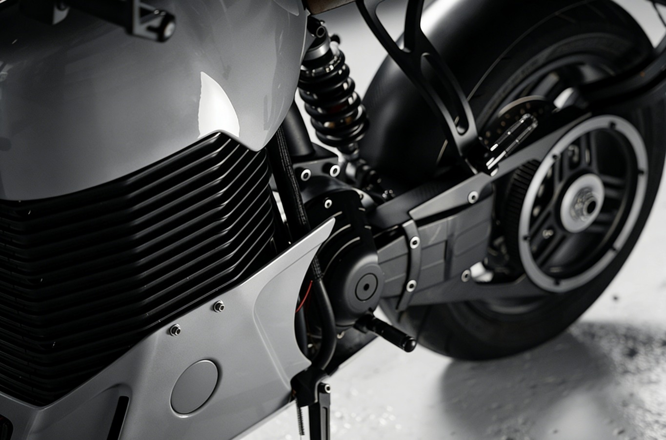
High-RPM EV Gears: Eliminate Whine with ISO 4-5 Precision
The shift from gasoline engines to powerful electric motors has changed the stresses that hit motorcycle drivetrains. Electric motors deliver instant torque and quick acceleration, but they push rotating parts to speeds well above 10,000 to 15,000 RPM. At such levels, ordinary industrial gears quickly hit their limits. They overheat, make a loud noise, or suffer sudden surface damage. DD Gear specializes in custom high-accuracy transmission parts and knows that lasting performance at high speeds comes down to tiny details in gear design. The Theoretical Challenges of High-RPM Transmission High-performance electric motorcycles depend on single-speed reduction setups to handle fast-spinning motors. These differ from classic motorcycle gearboxes because they face steady, rapid stress cycles without shifts. Rotational Dynamics and Centrifugal Force Mass Moment of Inertia: High RPM turns the gear mass into a heavy spinning object. This inertia slows the bike’s response when power comes on. Centrifugal Stress: Very fast rotation creates a strong outward pull. It bends tooth shapes by only a few microns, yet that small change throws off the proper contact area and leads to heavy edge pressure. Lubrication Fling-off: Fast-moving surfaces fling oil away from the teeth. Special finishes become necessary to hold a steady oil layer in place. The Impact of Transmission Error (TE) In fast e-axles, tiny errors in tooth form create transmission error. These small flaws repeat at high frequency and shake the gearbox casing. That shaking produces the sharp, annoying whine often heard in lower-quality electric systems. Cutting down this error calls for more than basic precision. It needs tooth shapes adjusted specifically to match the electric motor’s torque pattern. Advanced Metallurgy: The Foundation of Endurance A gear lasts only as long as the metal it comes from. Precision gear setups in electric motorcycles need materials that combine very hard surfaces with cores able to take shocks. Case-Hardened Alloy Steels DD Gear chooses better-than-standard steels for demanding high-torque jobs: 18CrNiMo7-6: This carburizing steel handles heavy loads well. It gives strong toughness inside and fights surface fatigue. 20MnCr5: This steel strikes a good balance between strength and resistance to sudden impacts. It suits many mid-drive reduction setups. Optimized Heat Treatment Profiles Long life comes from a careful heat treatment that builds a clear hardness change from outside to inside: Surface Hardness (58–62 HRC): The hard outer layer stands up to pitting and rubbing wear during high-speed running. Core Toughness (35–45 HRC): The softer inner part flexes enough to take sharp torque jumps in hard launches without breaking. Controlled Case Depth: Keeping the hardened layer depth within extremely small range keeps every gear in a batch working the same way. Professionals often turn to SAE International papers for detailed looks at how alloy makeup influences fatigue over many cycles. Precision Finishing and Micro-Geometry Optimization High-end electric bikes need gears that run quietly yet stay strong. That means finishing tooth surfaces to a very smooth, almost mirror finish to cut friction and heat buildup. Precision Tooth Grinding Regular hobbing falls short for high-speed electric motorcycle drivetrains. Grinding becomes essential to reach: ISO Grade 4–5 Accuracy: This level keeps pitch and profile errors very low. Vibration drops sharply even when the motor runs fast. Ra 0.4 μm Surface Roughness: Smoother tooth faces lower friction spots. That becomes the main way to stop oil from getting too hot in tight gearboxes. Customized Micro-Geometry Modifications No gearbox casing stays perfectly stiff. Heavy loads bend shafts and squeeze bearings. DD Gear adjusts tooth shapes to handle these actual deflections: Crowning: A gentle curve along the tooth length keeps the contact area in the middle even when shafts lean a bit. Tip Relief: Taking off a small amount of material at the tooth top creates a gentle start to meshing. It stops the harsh clash that builds noise at high speeds. Lead Correction: Slight changes to tooth direction correct for twisting of the input shaft under full motor torque. Power Transmission Engineering often discusses how ground gears improve performance in vehicle applications. Real-World Application Scenarios Small-module, high-accuracy gears make many electric motorcycle designs possible. Mid-Drive High-Speed Reducers The Application: A 15kW mid-drive motor turns at 12,000 RPM and feeds into a two-stage reduction before the chain. The Problem: The first spur-gear version created a loud whine during normal city riding at 40–60 km/h. The first-stage pinion also showed early pitting. The Customized Solution: A custom helical gear pair with carefully chosen helix angle and ISO Grade 4 grinding cut the whine by more than 6 dB. Lower friction added 2–3% to battery range. High-Torque Hub-Motor Planetary Sets The Application: A small planetary gear unit sits inside the rear wheel hub of an e-moped. The Problem: Extra unsprung weight and poor cooling space made regular planetary gears run too hot and fail on long uphill sections. The Customized Solution: High-torque planetary gears from 18CrNiMo7-6 steel used a thin-walled ring gear to save mass. Precision-ground planets kept efficiency high and avoided overheating issues. The DD Gear Advantage: Mastering Customized Precision Since 2010, DD Gear has worked closely with new industries. The focus stays on small-module high-precision gears (modules 0.3 to 1.5), where average quality never suffices. Our Customized Service Commitment Requirement Collection: We start with your 2D/3D drawings or checked physical parts to learn your torque and noise goals. Engineering Optimization: Our engineers propose changes to tooth forms and materials that fit your exact high-RPM working conditions and boost durability. Rapid Prototyping: High-accuracy samples arrive in 2–3 weeks, so your development team can test quickly instead of waiting months. ISO & IATF Quality: We follow ISO 9001 and IATF 16949 rules. This helps ensure our parts align with strict automotive standards for reliability and consistent performance. Ready to remove gearbox whine and make your e-motorcycle drivetrain last longer? Reach out to DD Gear now for a custom transmission answer that drives progress forward! WhatsApp: +86 182 5798 1010 | Email: support@ddgear.com FAQ Q: Why are helical gears generally preferred over spur gears for high-speed e-motorcycles? A: Helical teeth come into contact slowly instead of suddenly. That cuts shock and shaking, which greatly reduces the sharp whine heard when motors exceed 8,000 RPM. Q: Can gear precision actually influence the battery range of an electric motorcycle? A: Yes. Switching from common Grade 7-8 gears to custom-ground Grade 4-5 versions lifts drivetrain efficiency by 1% to 3%. For an electric vehicle, that gain means extra kilometers on each charge. Q: What is the most durable material for a pinion gear facing 15,000 RPM? A: Case-hardened alloy steels such as 18CrNiMo7-6 or 20MnCr5 work best. They deliver the hard surface needed to stop pitting and keep a strong core that stands up to sudden motor torque. Q: How does DD Gear handle the heat treatment distortion common in small-module gears? A: We rely on special fixtures during heat treatment. When needed, we grind the teeth after hardening to fix any warp and hold sub-micron precision.

Zero Tolerance for Error: Why Surgeons Trust Zero-Backlash Gears in Medical Robotics
In the modern operating room, the distance between a successful procedure and a critical complication is often measured in microns. As surgical robots become the standard for minimally invasive procedures, the demand for absolute mechanical precision has reached an all-time high. At the heart of these life-saving machines lies the transmission system—specifically, small-module precision gears that must translate a surgeon’s subtle hand movements into fluid, tremor-free robotic action. DD Gear has spent over 15 years perfecting the science of “Drive & Durable” motion, focusing on the high-precision requirements of emerging industries like medical robotics. We understand that in a surgical environment, there is zero tolerance for error, which is why our customized high-precision gear solutions are engineered to eliminate “lost motion” entirely. Defining Backlash and Its Impact on Clinical Outcomes In mechanical engineering, backlash is the clearance between mating gear teeth. While standard industrial applications may tolerate a few arc-minutes of play, surgical robotics requires near-zero backlash to ensure that control inputs reach the end-effector without delay or vibration. Why “Low Backlash” Isn’t Good Enough for Surgeons When a robotic arm performs a delicate suture or a resection near critical anatomy, any loose space in the gear line leads to: Wobble and Tracking Errors: The robotic path deviates from the intended trajectory, forcing constant controller retuning. Haptic Feedback Distortion: Surgeons rely on force control; backlash masks the tactile resistance of biological tissues. Micro-vibrations: High-speed electric motors spinning at 15,000 RPM can excite resonances if the gear mesh is not perfectly tight. The Theoretical Foundation of Lost Motion and Torsional Stiffness Mechanical play is the primary enemy of “repeatable spots” in robotics. Achieving extremely low level tolerance requires gears with high torsional stiffness—the ability to resist twisting under load. By utilizing customized high-stiffness planetary gear reducers with integrated output shafts, engineers can distribute loads across multiple teeth simultaneously, which inherently increases stiffness and reduces the risk of positional artifacts. DD Gear: customized Engineering for Surgical Actuators Standard off-the-shelf components often fail to meet the strict Noise, Vibration, and Harshness (NVH) targets required for hospital environments. At DD Gear, we do not offer a standard catalog for medical robotics; instead, we deliver customized solutions that fit specific duty cycles and space limits. Building-to-Print for Complex Joint Architectures Surgical robots utilize monoblock integrated gear-shaft assemblies for robotic wrist actuators to reduce assembly joints and improve overall alignment. Our customized manufacturing process includes: Requirement Collection: Reviewing detailed 2D/3D drawings or physical samples. Optimization: Tweaking lead corrections and profile shifts to minimize loaded transmission errors (TE). Rapid Prototyping: Delivering high-precision samples in just 2–3 weeks to support tight R&D schedules. Material Selection: From Carburizing Alloy Steels to Non-Magnetic Options The durability of a medical drivetrain depends on the harmony between surface hardness and core flexibility. High-Load Joints: We use case-hardening steels like 18CrNiMo7-6 or 20MnCr5, achieving a surface hardness of 58–62 HRC to fight wear while maintaining a shock-absorbing core. Nitriding for Stability: For lighter instrument stages, nitriding provides a hard surface with almost no distortion, preserving extremely low tolerances. Non-Magnetic Requirements: For robotic modules operating near MRI scanners, we provide customized gears made from austenitic stainless steel or aluminum bronze to eliminate magnetic interference. Application Scenarios: Where Accuracy Saves Lives Precision gears are the “silent support” in automated medical setups. Understanding where these gears are applied helps differentiate high-performance systems from basic automation. Minimally Invasive Instrument Modules In the “wrist” of a surgical robot, customized sub-miniature helical gears for multi-axis robotic articulators must operate in a housing no larger than a coffee mug. These gears enable the multi-degree-of-freedom movement required for deep-cavity surgery and ensure that the instrument tips remain stable even when the motor reverses direction hundreds of times per minute. For more information on the evolving standards of surgical robotics, you can explore the National Center for Biotechnology Information (NCBI), which details the integration of mechanical precision in robotic-assisted surgery. MRI-Adjacent Positioning and Imaging Tables Diagnostic systems, such as CT and MRI scanners, require high-torque performance and compact designs for moving patient tables. DD Gear provides customized anti-backlash worm gear pairs for MRI-compatible patient positioning tables because they offer: Self-Locking Safety: Ensuring the table holds its position near the scanner gantry even if power fails. Acoustic Excellence: Operating at levels below 60 dB to maintain patient comfort in quiet hospital wards. Smooth Motion: Reaching surface roughness levels of Ra 0.4 μm through precision grinding to eliminate “motion ripples” that could cause image artifacts. Technical Excellence: The DD Gear Customized Manufacturing Process How do we guarantee that our gears meet the “Zero Tolerance” requirements of the medical industry? It comes down to sub-micron verification and advanced finishing. Achieving High ISO Grade Accuracy through Advanced Grinding DD Gear utilizes Reishauer and Klingelnberg grinders to achieve ISO 1328 Grade 4–5 precision for specific projects. This level of accuracy is essential for reducing transmission errors that cause high-pitched whines in high-speed electric motors. Micro-Geometry Modifications for Vibration-Free Operation Basic tooth shapes are often insufficient for the high-duty cycles of surgical robots. Our engineering team applies specific modifications: Tip Relief and Crowning: rounding tooth tips and curving the tooth face to prevent concentrated loads and ensure gentle entry during meshing. Lead Corrections: Small adjustments that distribute torque evenly across the gear face, extending the service life by 30%. To understand the deeper physics of how tooth geometry affects sound and vibration, refer to the technical research published by Nature: Scientific Reports on gear transmission error and noise control. Quality Control: Verification on Klingelnberg Measuring Centers We don’t just promise precision; we verify it. Customized batch undergoes detection of key features. Using Klingelnberg P26/P40 gear measuring machines, we verify: Tooth Profile and Lead Deviation: Ensuring deviations is at an extremely low level. Backlash Windows: Monitoring play to ensure it meets the startup’s specific joint requirements. Concentricity and Runout: Essential for stable alignment in high-speed rotor shafts. The Path from Prototype to Production In the fast-changing world of medical technology, speed is as important as accuracy. DD Gear bridges the gap between a design concept and a stable mass-production part through our streamlined, customized process. Agile Prototyping: We offer flexible MOQs, handling everything from a single prototype to medium-sized production runs. Build-to-Print Precision: We manufacture directly from client drawings, ensuring that the final component integrates seamlessly into existing housings. Global Reach: With certifications like ISO 9001 and IATF 16949, we serve medical OEMs in over 30 countries, ensuring that every gear hits high automotive and industrial standards. Ready to Drive Your Medical Innovation Forward? Don’t let mechanical play compromise your surgical precision. Contact DD Gear today to develop a customized small-module gear solution tailored to your exact torque, noise, and zero-backlash requirements. [Get a Free Quote & Engineering Consultation Today] FAQ Q: Can DD Gear provide non-magnetic gears for MRI-conditional environments? A: Yes, we provide customized gears using non-magnetic austenitic stainless steel and aluminum bronze specifically for modules adjacent to MRI scanners. Q: What is the primary cause of gear whine in surgical actuators? A: Gear whine is typically caused by transmission error resulting from minute tooth flank deviations. At speeds over 10,000 RPM, deviations of just a few microns can create a significant whine. Q: Why are small-module gears (0.3–0.8) necessary for modern medical robotics? A: They allow designers to fit large torque and high reduction ratios into very compact joint actuators, preventing the gearbox from taking up unnecessary room in the surgical field. Q: How long does it take to receive a customized gear prototype? A: We typically deliver customized gear prototypes within 2–3 weeks, allowing engineering teams to iterate on designs quickly.
Precision at the Warehouse: Why AGV Reliability Starts with High-Load Precision Gears
Modern warehouses run on continuous automated processes. Automated Guided Vehicles (AGVs) and Autonomous Mobile Robots (AMRs) form the backbone of daily material movement. These machines work without breaks, yet their mechanical parts face constant heavy strain. The drive unit stands as a central element in every mobile robot. High-load gearsets inside that unit often decide whether operations continue smoothly or face expensive interruptions. DD Gear focuses on designing and producing small-module, high-precision gears. These components target the tough operating patterns found in robotics and logistics. The company has concentrated on custom transmission solutions. Accuracy, long service life, and low noise remain the main priorities. The Challenge of High-Frequency Warehouse Operations AGVs in warehouses do far more than simple travel. They execute repeated high-torque actions in narrow aisles. This pattern places unusual demands on conventional gear systems. Understanding the 24/7 Start-Stop Cycle Logistics robots work under conditions quite different from standard industrial trucks. Constant Reversals: AGVs change direction often. They accelerate and decelerate quickly while moving between storage racks and picking stations. High Torque at Low Speed: Shifting pallets that weigh 600–800 kg requires high-torque density from custom wheel-hub planetary gearsets, even at slow speeds. Thermal Accumulation: Nonstop running leaves almost no downtime for cooling. Heat builds steadily, raising the chance of oil breakdown and surface damage on gear teeth. The Impact of Premature Wear Gears without sufficient precision or material strength show several types of failure. Pitting and Micro-spalling: Intense contact pressure damages tooth surfaces over time. This leads to audible gear noise and increased vibration. Backlash Growth: Worn teeth create larger gaps between meshing pairs. The added clearance causes lost motion. Positioning then becomes less reliable, and closed-loop controls may trigger frequent encoder faults. NVH (Noise, Vibration, and Harshness): Excessive gear mesh noise in shared workspaces creates an uncomfortable setting and lowers worker focus. Research on material fatigue in repeated high-cycle applications appears regularly in ScienceDirect on gear wear and tribology. Engineering Reliability into Small-Module Precision Gears Standard catalog parts seldom withstand these conditions for long. Custom high-precision designs become necessary to address wear from frequent use. The Shift to Small-Module Precision Contemporary robot layouts require tight packaging. The field has moved toward small-module precision gears, customized ultra-fine pitch gears (modules 0.3–0.8mn) for compact actuators. Fine teeth produce very high reduction ratios inside housings about the size of a coffee mug. Torque Density: Small teeth support detailed power transfer in compact wheel-hub assemblies. Integrated Design: Gear and shaft made as one piece, cutting down assembly connections. Alignment improves, and vibration drops noticeably. Planetary Gearsets for Compact Power Heavy-duty AGV forklifts and warehouse robots frequently rely on planetary gear drives. Load Sharing: Several planet gears carry force at the same time. This arrangement handles much higher torque than a single spur gear of equal diameter. Coaxial Efficiency: The inline layout fits neatly into drive wheel hubs. Material Science: The Foundation of Durability Gear reliability depends heavily on the alloy and its treatment. DD Gear selects advanced steels and applies careful heat processes. Every custom gearset then endures millions of cycles. Selecting High-Load Alloy Steels AGV transmissions need materials that combine a hard exterior with a tough interior. 18CrNiMo7-6 & 20MnCr5: These case-hardening steels form a very wear-resistant surface. The core stays flexible enough to take sudden impacts. HRC 58–62 Hardness: Carburizing and quenching produce this surface rating. It resists contact fatigue and surface dents effectively. Precision Heat Treatment Standards Heat treatment largely determines final gear performance. Controlled Carburizing: The method builds deep hard layers, up to 1.2 mm thick. Surface wear in drive wheels decreases markedly. Nitriding for Stability: Lighter gear stages that demand minimal shape change benefit from nitriding. Tight tolerances hold steady through the process. Micro-Geometry Modifications Even premium steel fails without a proper tooth shape. Subtle changes to the tooth profile improve results. Tip Relief: Rounded tooth tips allow smooth entry and exit from contact. Impact noise drops. Crowning: A slight curve along the tooth face avoids edge stress peaks. Working life extends significantly. Lead Corrections: Small adjustments spread torque more evenly across the face. Early pitting risk falls. Where High-Precision Gears Solve Real Problems Theory matters, yet field results show the practical worth of these custom precision gears for AGV. Pallet-Handling AGVs in Distribution Centers Large logistics facilities run robots that transport loads up to 800 kg across concrete floors around the clock. Problem: Older spur gears showed pitting on tooth surfaces. Noise often rose above 60 dB, disturbing nearby workers. Solution: A customized multi-stage planetary-helical gearbox for high-torque AGV steering and drive lowered sound to the mid-50 dB range. Torque capacity increased at the same time. Result: Drive unit maintenance periods doubled. Unplanned stops decreased by nearly half. Precise Positioning in AMR Picking Robots Pick-and-place units need consistent extremely high accuracy when aligning with storage shelves. Problem: Standard gearboxes developed growing backlash. The robot swayed during fast travel. Controllers required ongoing adjustments. Solution: Customized zero-backlash precision ground gears for sub-millimeter positioning accuracy can reach ISO Grade 4–5 accuracy. Torsional stiffness rose noticeably. Result: Drive behavior stabilized. Positioning held steady. Robots moved faster and handled more tasks per shift. Current developments in robot drive systems receive regular coverage in Machine Design industry reports. The DD Gear Advantage: Why Customized Engineering Matters DD Gear avoids standard product catalogs. High-performance transmission arises from parts shaped to match the real operating demands of each robot. Build-to-Print Precision DD Gear specializes in build-to-print small-module gear manufacturing for OEM robotics projects. Production uses customer drawings or confirmed samples directly. Accuracy Verification: CNC gear measuring equipment checks every part. Some specific projects can achieve ISO 1328 Grade 4–5 levels, depending on design requirements and application needs. Rapid Prototyping: Custom gear prototypes ship in 2–3 weeks. This timing fits urgent development schedules. Comprehensive Customization Services extend past basic dimensions. Material Selection: Alloys match the specific load environment, including non-magnetic choices for medical robotics. Optimization: Tooth geometry receives adjustments for the lowest possible NVH profile. Flexible Volumes: Production scales from single test pieces to moderate batch runs. Master the Future of Motion with DD Gear Does your AGV fleet show early wear or high noise levels? Improve motion control with DD Gear’s detailed engineering. The team stands ready to create a custom gear solution suited to your torque, noise, and space needs. Contact DD Gear Today for a Free Quote and Rapid Prototyping! FAQ Q: What accuracy grades are required for modern AGV drive units? A: High-performance AGVs generally need ISO 1328 Grade 4–5 precision ground gears. These levels support low noise and reliable positioning. Q: Why is small-module design preferred over larger gear modules? A: Modules from 0.3–0.8 pack large torque and high reduction ratios into very small spaces. Gearboxes then avoid taking up extra room inside the robot. Q: How does carburizing improve gear lifespan? A: Carburizing forms a hard outer layer at HRC 58–62. It fights wear effectively. The flexible core absorbs shock loads from frequent starts and stops. Q: Can customized gears help with battery driving range? A: Yes. Switching from standard Grade 7–8 gears to precision Grade 4–5 versions raises drivetrain efficiency by up to 1.2%. Large fleets see meaningful power savings and longer run times per charge.
Unlocking the Power of Spiral Bevel Gears in Robotics and Automation
The world of current factory tech moves toward quicker paces, smaller sizes, and almost quiet running. In this quick-shifting area, how well one exact gear works can decide if a detailed setup runs with tiny-level precision or hits a major failure. As a top maker of precision gears, DD Gear knows that switching from old machine systems to smart automation calls for a strong grasp of modern drive parts. Among them, precision spiral bevel gears have become a vital fix for handling angle-based power flow in the toughest settings. The Theoretical Foundation of Spiral Bevel Gear Technology To grasp how precision spiral bevel gears push fresh advances, one must first look at their special shape and machine actions compared to usual gear kinds. Geometric Distinction and Meshing Kinematics Unlike straight bevel gears, which have straight teeth lined up along the cone line, spiral bevel gears use bent teeth. Curved Tooth Form: The teeth form on a cut cone face. This setup lets power change direction through crossing shafts, often at a 90-degree turn. Gradual Engagement: The spiral shape makes teeth connect step by step instead of all together. As a result, it cuts down on hits and heard sounds during fast spins. High Contact Ratio: Due to the twist curve, several teeth stay in touch at the same time. This spreads the force better across the gear surface. Performance Benefits in High-Speed Applications The basic strengths of precision spiral bevel gears turn straight into clear gains for automated setups. Increased Load Capacity: The bigger tooth count lets these precision gears take on more twist force than straight-cut ones of the same size. Superior Thermal Stability: Well-planned spiral teeth boost contact steadiness. They lower spot slide stress and heat buildup during round-the-clock runs. Acoustic Excellence: A right-shaped design can drop running sound by more than 50% against straight-tooth types. This matters a lot for spots where people and robots work side by side. For more on the motion studies used to improve these touch patterns, workers in the field often check spots like the IEEE Xplore. It holds broad studies on flight-level gear drive systems. Integration in Modern Robotic Systems In robotics, where space is tight and exactness is key, precision spiral bevel gears offer the main link between motors and motion. Precision Drives for Humanoid and Collaborative Robots Human-like robots need joint drives that stay light yet handle tricky moves. Low-Backlash Positioning: To hit repeated spots within ±0.02 mm, loose play must be removed through low-backlash precision gears for humanoid joints. Right-Angle Joint Actuators: Precision spiral bevel gears often fit into hip, knee, and shoulder links to keep a thin drive outline while giving high twist density. Smooth Motion Trajectories: Step-by-step tooth linking stops tiny shakes that might cause arm sway in fine jobs. Surgical Robotics and Medical Automation Surgery robots call for the top levels of dependability and fit with the body’s needs. Micron-Level Force Control: Small-module precision spiral bevel gears for surgical actuators allow even, steady force flow in small tool drives used for low-cut methods. Compact Right-Angle Transmission: These precision gears let image heads and surgery parts turn just right in tight medical frames. Material Compatibility: Special uses, like robots near MRI, often use customized non-magnetic alloy precision gears for MRI environments from aluminum bronze or austenitic stainless steel to avoid field mix-ups. Spiral Bevel Gears in Industrial Automation Past robotics, the drive for smart plants has raised the part of precision gears in regular automation tools. High-Speed CNC Machining and Feed Systems Exactness cannot be traded in CNC heads and extra drives. Spindle Stability: High-precision case-hardened alloy steel gears for CNC spindles work in turn tables and tool switch setups to shift shaft paths without losing cut precision. Extended Service Life: By picking case-hardened alloy steels, these precision gears can stand up to quick back-and-forth moves and 16-20 hours of daily work. Vibration Control: Cutting transmission error (TE) leads to the top surface ends on laser or plasma cut pieces. Automated Guided Vehicles (AGVs) and Logistics The inside moving field counts on tough parts for non-stop storage settings. Wheel-Hub Reduction: High torque density gearsets for AGV wheel-hub drives let AGV wheel units pack strong turn force into a spot as small as a coffee cup. Shock Load Resistance: These gears get built to take sudden hits—often 400-600 Nm—during quick stops or with heavy loads. Silent Fleet Operation: Lowering gear sounds matters for late shifts and mixed pick areas with people and robots. Design workers seeking more on basic machine plans and new automation ways may find good tips at Design World. It stands as a main spot for the design work group. Manufacturing Excellence and Material Science How well a precision spiral bevel gear works comes down to its metal makeup and the sharpness of its manufacturing process. Advanced Metallurgy and Heat Treatment At DD Gear, the lasting strength of each part lies in tight metal rules. Case-Hardened Alloy Steels: Main picks include 18CrNiMo7-6 high-load carburizing gear steel and 20MnCr5. They stand out for their mix of high outer hardness and a strong center. Surface Hardness: Carburizing and quick cooling push the outer layer to HRC 58-62. This gives great fight against dents and touch wear. Precision Finishing: Sharp gear grinding hits ISO 1328 Grade 4-6 levels. This step proves key for cutting sounds and raising power flow. The Importance of Customized Engineering Basic ready parts often fall short on the strict needs for shake control and room fitting in current machines. Application-Specific Geometry: Makers can tweak tooth side traits, such as crowning and tip relief, for better power shift. Build-to-Print Solutions: Customized precision gear groups get planned based on exact force ranges and case limits. They fit just right for any motor or frame. Rapid Validation: DD Gear backs quick item rounds by sending sharp customized test pieces in as few as 2-3 weeks. Conclusion: Driving the Future of Precision As robotics and automation keep growing, the need for small, effective, and quiet drive fixes will only rise. Precision spiral bevel gears lead this change. They bring the steadiness and work level needed for the next wave of smart machines. By centering on customized gear solutions for industrial automation, DD Gear stays set to help world makers with precision gears that give unmatched accuracy and strength. Whether building a two-legged robot or a fast CNC cut line, picking the right gear tech forms the base of machine wins. Precision spiral bevel gears provide high load capacity and quiet operation for robotics. Contact DD Gear today to customize your high-performance gear solutions! FAQ Q: Why are spiral bevel gears preferred over straight bevel gears in robotics? A: Precision spiral bevel gears have bent teeth that connect step by step. This leads to even motion, less sound, and a bigger twist hold, which proves vital for robot joint steadiness. Q: What materials are best for high-torque spiral bevel gears? A: Strong alloy steels like 18CrNiMo7-6 or 20MnCr5 stand as usual picks. They give a wear-resistant, hard surface with a tough center to take in high loads. Q: Can spiral bevel gears be used in MRI-compatible medical robots? A: Yes, they can get made as customized sets using non-magnetic stuff like aluminum bronze or austenitic stainless steel to avoid field issues. Q: What is the lead time for a customized gear prototype at DD Gear? A: For most sharp, customized tasks, we can send test pieces within 2–3 weeks to aid quick checks of your plans.
Precision in Motion: The Role of Custom Precision Round Gear Racks in Modern Automotive Engineering
The quiet move toward electric vehicles and driverless cars has raised the bar. Now the gap between a comfortable drive and a breakdown often comes down to clearances measured in microns. Car makers have largely left behind big, heavy gasoline engines in favor of smaller, quicker electric motors. Because of this change, turning rotary power into straight-line motion using small-module precision gears for EV transmissions has grown more important than ever. Round gear racks stand out in this shift. The Theoretical Framework of Round Gear Racks in Linear Actuation In current vehicles, nearly all straight-line movement comes from fast-spinning electric motors. A round gear rack pairs with high-speed e-motor input shafts to change that spinning force into controlled linear travel. This makes them especially useful where parts must move inside round seals or narrow tube-like spaces. DD Gear concentrates on getting this meshing connection right. How well power transfers in these setups depends mainly on the shape of the teeth and tiny surface features. A custom-made round rack brings several practical gains: Reduced Friction Waste: Well-shaped tooth flanks keep heat low even after thousands of rapid cycles. Enhanced Torsional Stiffness: The round section stands up to bending and twisting much better than flat or box-shaped ones. Zero-Backlash Integration: High precision grinding makes each movement repeat within a micron or less. Common Applications in Electric Power Steering (EPS) Many present-day electric vehicles use motors that spin between 12,000 and 18,000 RPM. Those speeds need heavy reduction through low-NVH gears for electric drive units before they can deliver a helpful steering force. Modern Electric Power Steering systems are now widely adopted across global platforms, as detailed by Bosch Mobility. High-Torque Steering Assist Today’s EPS units face very large shock loads, yet still need to feel natural to the driver. Custom round racks deal with several tough design issues: The Problem: Bigger electric vehicles carry heavy battery packs. That weight adds considerable strain to the steering column. The Solution: Racks built from case-hardened steels like 20MnCr5 or 18CrNiMo7-6 get deep surface hardening to 58-62 HRC. They then manage shock loads of 400-600 Nm without developing pits or surface failure. Precision and Customized Service: Changing the helix angle and pressure angle on the teeth removes any jerky or stepped feeling. The steering stays smooth and predictable even at highway speeds. Redundant Actuation for Autonomous Driving Vehicles built for Level 3 or Level 4 self-driving need backup mechanical paths for steering. Small-module high-precision gears drive backup actuators that connect to the round rack when the main system fails. The Problem: Regular gears leave noticeable free play. During automatic lane keeping, that play causes shaky steering. The Solution: Teeth finished to sub-micron accuracy create a true zero-backlash fit. The car’s control system can then make very small corrections with repeatability of ±0.02 mm. Safety and Braking: The Role of Electronic Parking Brakes (EPB) Safety parts must work reliably across the whole vehicle life, frequently past 200,000 cycles. Emergency Braking and Locking Mechanisms The parking lock and its related racks hold the vehicle steady on slopes. Application Scenario: Selecting “Park” causes a motor to drive case-hardened small-module automotive gears to push a round rack or similar part into the locked position. Problem Solved: The mechanism has to withstand sudden bumps or jolts without releasing. Technical Solution: High-load case-hardening steels form a wear-resistant outer layer while the inner core stays tougher at 35-45 HRC. This combination prevents tooth breakage under impact. Braking-by-Wire Actuators Brake-by-wire systems replace fluid lines with electric actuators. The Problem: Any delay in the mechanical chain lengthens stopping distances. The Solution: Small-module high-precision gears for EV reducers matched with custom round racks cut transmission error sharply. Brake pads then press against the rotor within milliseconds of pedal input. Interior Comfort and Precision Convenience Systems Electric cars turn the cabin into more of a living area. Customized Power Seat Adjusters Round gear racks work well for power seats that move in several directions—height changes, lumbar support, and more. Application Scenario: The rack sits inside the seat rail and lets the seat slide forward or tilt. Problem Solved: Older seat systems frequently show jerky stick-slip movement and produce a clear humming noise. Technical Detail: Special tooth details, such as crowning and tip relief, keep the contact patch centered. This remains true even when the seat frame bends slightly under a passenger’s weight. Intelligent Sunroof and Liftgate Actuators Panoramic sunroofs and power tailgates require long travel in a small space. Round racks handle that requirement effectively. Application Scenario: A motor, reduction gear, and round rack work together to move heavy glass or metal panels open and closed. Problem Solved: Saving weight remains a constant goal because it directly affects driving range. The Solution: DD Gear selects strong, lighter materials and grinds surfaces to Ra 0.4 μm. This allows smaller motors and gearboxes while still carrying the necessary loads. The Strategic Importance of Customized Precision Standard catalog parts seldom meet the tough targets for weight, noise, and packaging found in modern car platforms. Customized precision gear makes the real difference in this competitive field. Why Customized Engineering Matters NVH Control: Small mistakes in tooth shape produce the sharp whine heard in some early electric cars. Careful flank polishing and lead correction can reduce noise by as much as 6 dB. Efficiency: Better meshing between reduction gears and racks raises drivetrain efficiency by up to 1.2%. That gain adds meaningful distance to each battery charge. Durability: Round-the-clock dependability, once mainly needed for warehouse robots, now applies to key safety parts in everyday passenger cars. About DD Gear: Powering the Future of Motion DD Gear focuses on small-module high-precision gears and transmission components. The company works in the area of future motion—covering robotics, electric vehicles, and smart automation. Stock items are not offered. Every job follows a build-to-print model, turning customer 2D or 3D drawings into finished mechanical parts. 15+ Years of Experience: Long-standing trust from major carmakers and large global partners. Advanced Capabilities: Reishauer and Klingelnberg grinders enable ISO Grade 4–5 accuracy for specific projects, depending on design requirements and application needs. Fast Iteration: Prototypes ship in 2–3 weeks to fit tight development timetables. Contact Us Today for a Customized Transmission Solution Whether the project involves advanced electric power steering or a precise actuator for medical equipment, the DD Gear team is prepared to assist. We work together on gear profiles, material choices, and heat-treatment steps. Contact Us for a Free Quote | WhatsApp: +86 182 5798 1010 FAQ Q: What is the primary cause of gear whine in automotive linear actuators? A: Transmission error stands as the main reason. Tiny differences in tooth form make teeth strike rather than slide past each other cleanly. At speeds above 10,000 RPM, deviations of only a few microns turn into noticeable sound. Q: Why are round gear racks preferred over flat racks in tight automotive spaces? A: Round racks support coaxial arrangements and move easily through cylindrical bushings. That design simplifies sealing and fits naturally into the tube-shaped housings used in steering systems and seat adjustments. Q: Can customized round gear racks improve EV battery range? A: Yes. Precision grinding lowers friction, and careful mesh adjustment raises transmission efficiency. Together, these changes help the vehicle travel farther on one charge. Q: What materials are best for high-load automotive round racks? A: Alloy steels such as 18CrNiMo7-6 and 20MnCr5 remain the go-to materials. They deliver a hard outer surface of 58-62 HRC for wear resistance and a more flexible core that handles sudden impacts without cracking.
LOVE TO HEAR FROM YOU GET IN TOUCH!
Please fill out the form below and we will get back to you as soon as possible.