- support@ddgear.com
- North 3F, Building 13-2, Zhixin Park, NO.1099 Xianhua South Street, Wucheng, Jinhua, Zhejiang, China.

Automatic Door
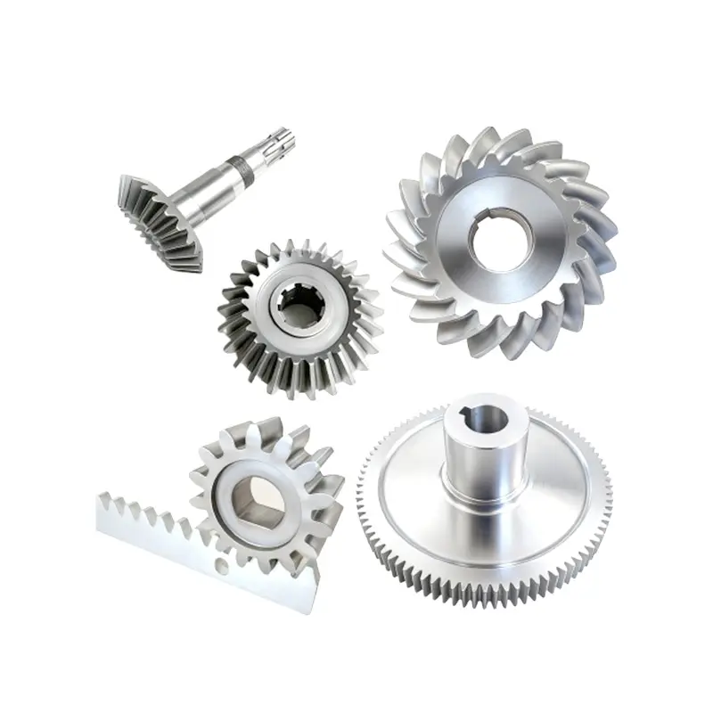
Custom Gears for Sliding, Swing & Industrial Doors | DD Gear
Automatic Door Gear from DD Gear is a range of custom-designed, small- to medium-module gears and shafts used in automatic sliding doors, swing doors, revolving doors and industrial doors (sectional, rolling, high-speed doors). In these systems, compact electric motors drive gearboxes and gear trains that must deliver high starting torque, smooth motion and very low noise while opening and closing heavy door leaves hundreds or thousands of times per day. Typical automatic door operators use one or more stages of spur and helical gears in combination with worm gears or bevel gears. Spur gears provide simple, efficient torque transfer for intermediate stages. Helical gears, with their angled teeth and higher contact ratio, help achieve quieter and smoother running, which is critical in hotels, hospitals, offices and residential buildings. Worm gears are often used for high reduction ratios and self-locking behavior, improving safety when the door is at rest and reducing backdrive from wind loads or manual pushing. In some operators, bevel gears change shaft direction between the motor, transmission and drive shaft or belt/chain. DD Gear manufactures Automatic Door Gears strictly on a custom, build-to-print basis. Using customer drawings or validated samples, we supply spur and helical pinions and gears, worm gears and worm wheels, bevel gears, gear shafts and related components for door operators. Through appropriate alloy steels, surface treatments, controlled heat treatment and precision machining, DD Gear helps door-operator OEMs and system integrators build drives that provide quiet operation, long life and reliable performance in entrances exposed to dust, temperature changes and frequent cycling.Precision Gears Built for the Future.
Trusted by Global OEMs, Proven in Every Application.
Your Custom Gear Solution Starts Here.

LOVE TO HEAR FROM YOU GET IN TOUCH!
Exploring The Science of Precision Gears

How to Specify Gear Backlash and Tooth Thickness on Engineering Drawings
Give the assembly a gear backlash range and a reproducible test for it. Give the individual gears tooth-size limits that support that result. The final check is whether those limits work together at the permitted mounting conditions. Without it, a drawing can be perfectly readable and still leave the supplier unable to tell whether the pair will pass. These notes cover parallel-axis cylindrical involute gears. A worm drive, bevel set, or preloaded mechanism needs its own definition and test. The numerical examples explain the reasoning; they do not recommend a running clearance. Distinguish the gear requirement from the assembly requirement The inspection bench and the gearbox answer different questions. On the bench you can measure a loose gear’s tooth thickness. In the box you have a mesh, its mounting conditions, and a resulting clearance. That is the distinction to keep in view when specifying CNC transmission gears for a machine whose reversal behavior matters. Ask the drawing package two questions. Can the shop determine the permitted tooth size? Can the assembly inspector determine the permitted clearance? Finding an accuracy grade on the drawing doesn’t complete either answer. Its geometric-deviation controls still need to sit alongside the tooth-size and mesh requirements. Before calling a result backlash, trace what moved during the test. Perhaps the reading includes a bearing or coupling, or the measuring torque caused some elastic movement. Decide which of those effects the test is intended to include. Define the direction and conditions of backlash measurement A bare clearance number needs context. Specify its direction, units, and reference circle or radius. A transverse circular value, normal value, and angular reading cannot be substituted for one another. In particular, an indicator near the tooth tip is not reading a pitch-circle distance directly; the comparison needs a conversion. Imagine handing the procedure to an inspector who has never seen your fixture. They need the mating revisions and center distance, including tolerance, plus temperature and lubricant condition. They also need the measuring torque or load, which member to hold, and where to record movement. Supply that information with the test. Decide which positions around the pair must be checked. One convenient position cannot establish the tightest point elsewhere. If variation through rotation is part of acceptance, retain the observed minimum and maximum with their test conditions so the reading can be understood later. Establish the complete tooth geometry Keep the gear definition together in a tooth-data block. Alongside type, tooth count, pitch, pressure angle, and face width, identify any profile shift. The module and pressure angle also need their normal or transverse convention stated; it is an avoidable ambiguity. Circular thickness is an arc on a specified circle. A chordal measurement is straight and needs its measuring height. Writing just tooth thickness beside a number leaves both interpretations open. Settle which quantity is meant before calculating the limits. For an ideal unshifted spur gear with no thinning, reference-circle circular thickness is s = pi x m / 2. Module 2 gives approximately 3.142 mm. That is a geometric starting point. It becomes a finished-part requirement only after the design accounts for such matters as profile shift and the selected thinning allowance. Allocate tooth thickness through a tolerance analysis Now work through the permitted combinations. One end gives the tightest mesh, which still needs its required clearance. The other gives the loosest, which has to meet the reversal requirement. Carry the tooth sizes, mounting tolerances, deviations, and operating conditions through that reasoning before allocating the allowable size to each member. Splitting the thinning equally is a choice to justify. It isn’t the only choice. Where one member already exists, its verified limits constrain what you can ask of the new member. Make those inputs visible so a later drawing change doesn’t invalidate the allocation unnoticed. There is also the option of changing center distance in an external pair. That can increase backlash, with a corresponding change in mesh geometry. If the design uses housing adjustment, define its range and purpose. An adjustment made only to get an over-thick pair turning hides the original acceptance problem. Hypothetical calculation of the thinning contribution Take an ideal external spur pair at its reference center distance, initially without backlash. Reduce each member’s circular tooth thickness at its reference circle by 0.04 mm. The contribution from thinning is then 0.04 + 0.04 = 0.08 mm. There are no mounting errors, thermal changes, tooth deviations, or deflection in that sum. It is only the thinning contribution. Complete the rest of the analysis before assigning inspection limits; the sum alone cannot tell you whether a gearbox will run acceptably. Choose an inspection dimension the supplier can measure Discuss the proposed method before specifying a very narrow tolerance. Instrument access and measurement uncertainty matter as well as nominal geometry. Span, pin or ball, and chordal measurements each need enough information on the drawing for another inspector to reproduce the setup. Method What belongs on the drawing What to resolve with inspection Span Number of teeth spanned and dimension limits Contact of the anvils on the intended flanks Pins or balls Gauge diameter, arrangement, and dimension limits Placement, tooth-count effects, and access Chordal Chordal thickness, measuring height, and reference Suitability of the height reference The drawing must identify the pins used for a pin measurement. Their diameter affects the resulting dimension. Check the calculation for the actual helix and tooth count, and use a suitable between-pins or equivalent definition for internal teeth. A convenient external, even-tooth setup does not cover all three cases. Two inspection dimensions can create two acceptance decisions. If you show a converted circular thickness beside the shop measurement, mark its role clearly. Is it reference information, or must both limits be met? Work that out before the supplier has parts waiting for disposition. Build a drawing note set that can be inspected Use the component drawing to control tooth size and the assembly drawing to control mesh clearance. Connect them through part numbers and revisions. A note template can organize the information, although its numerical limits still require calculation and approval. Location Content to complete before release Tooth-data block Pitch, tooth count, pressure angle, helix data, profile shift Part acceptance note Measurement method, gauge size or span count, upper and lower limits Manufacturing note Final condition in which the limits apply Assembly note Mating revisions, center distance, backlash direction and range Test procedure Temperature, lubrication, measuring load, radius, and positions Try reading the span note without the rest of your calculation file. Can the inspector find the span count and dimension range? Now read the assembly note the same way. It needs minimum and maximum backlash plus the conditions for the reading. Include the mating geometry in the enquiry for custom manufacture. A supplier reviewing one drawing alone may have no way to recognize a conflict with the other member. Include finishing, datums, and functional verification Put a manufacturing condition beside the tooth-size requirement. A measurement before heat treatment, grinding, or coating may describe flanks that will subsequently change. Acceptance needs the specified final condition. Also check that the datums correspond to the bore, journals, and faces used to locate the gear in the assembly. Functional tooth thickness brings the effect of geometric deviations into the tooth’s effective meshing size. That explains why a local thickness reading may leave a meshing question unanswered. Agree how gear profile and lead inspection and the selected tooth-size measurement will address their respective parts of acceptance. If conforming components produce a failing assembly result, examine the setup before changing the drawing. Center distance, mounting runout, bearings, datum alignment, and measuring procedure are possible investigation points. Any resulting design change still needs revision control and another check of the tolerance analysis. Check the package before releasing the drawing Take one last look at the component drawing beside the assembly requirement. Can another inspector reproduce both checks? Do they apply to the same final manufactured condition? Does the proposed equipment have enough resolving capability for the limits you have chosen? Answer those questions before release. The public scope of ANSI/AGMA 2002-D19 covers tooth-thickness limits and measurement calculations, including their relationship with backlash in cylindrical involute gearing. Consult the full applicable controlled standard to complete the design. If the supplier proposes a customary allowance, review and state it explicitly instead of leaving it as an unwritten assumption. FAQ Can I specify zero backlash on an ordinary gear pair? Only after the design and its test account for the operating conditions, including thermal change, geometric variation, and elastic behavior. A preloaded arrangement needs a defined functional test of its own. Is tooth thickness the same as a span dimension? No. A span is taken across a specified number of teeth. Its relationship to tooth thickness follows the gear geometry and the selected measurement definition. Does a tighter accuracy grade guarantee lower backlash? No. The assembly still sees both gears’ tooth-size limits and their mounting conditions. Keep a separate mesh-clearance requirement even when the individual gear grade is tightly controlled. Should both mating gears have a tooth-thickness tolerance? Both need compatible controlled definitions. Use the verified limits of an existing or purchased member when allocating the allowable size of its mate. Prepare a drawing review with DD Gear For a manufacturing review, send the mating drawings together with the duty, quantities, center-distance limits, and proposed clearance test to DD Gear for a gear drawing review. Settle the feasible tooth-size definition and inspection scope before tooling. Approval of the design limits remains with the responsible designer.

How to Manufacture Custom Gears from Physical Samples Without Drawings
You don’t need an old drawing to manufacture custom gears from physical samples. You do need a new, approved definition before cutting the replacement. Measurement supplies the evidence for that definition; engineering review settles the intended dimensions and material. A first article can then be made, inspected, and tried in the assembly. Expect some work between measuring a worn tooth and deciding what its unworn form should have been. Consider what you can actually hand over. An intact gear with light wear gives the investigator much more to work with than a cracked hub and loose fragments. A production price agreed before anyone has assessed that evidence may rest on assumptions neither party has discussed. Gather the sample and its operating context Find the mating part before sending the sample away. It may have to answer a question about the mesh even though you intend to keep it. For replacement gears in CNC machines, say where the part works. Naming the spindle drive or rotary table is a better start than describing both simply as machine gears. Photographs, a machine reference, quantities, tooth count, and rough dimensions will start the discussion. Send the fragments too. The apparently unimportant broken piece may be the one that preserves a useful surface. Check where the duty figures came from. A motor nameplate value and a measurement at this gear are different inputs, so label yours. The oil used, any temperature observations, and what happened before the failure are worth including. There is no benefit in making an incomplete enquiry look complete. Leave a photographic record before cleaning changes the appearance of the damage. Preparation and testing can then be agreed with the recipient. Marking a surface for a hardness check may be acceptable; consuming the last useful fragment is a different decision. Make it deliberately. Separate measurable features from missing design information A measurement tells you the size of the sample now. The drawing must tell the machinist what size the replacement should be, with an acceptable range. Those numbers may differ at a worn bore or mounting face. Beside each proposed dimension, keep the measurement or reasoning that led to it. This is particularly helpful around mounting features. A shoulder measured from one face may tell you little about its relationship to the locating face. More readings from that same reference won’t fix the problem. An uncertainty register can stay quite small. Feature What is available What still needs agreement Tooth form Surviving flanks and mating part Intended geometry Bore and locating faces Present dimensions and shaft layout Nominal fit and datums Material Chemistry and hardness results Replacement specification Backlash Assembly observations Acceptance limits Someone with design authority still has to accept the assumptions in that table. Recover the tooth geometry Start by establishing what kind of gear is on the bench. The measurements for a spur or helical gear won’t supply a complete definition of a bevel gear or worm set. That remains true however convincing the scan looks on screen. On cylindrical teeth, the investigation has to resolve the tooth count, pitch system, pressure angle, thickness, and any profile shift. A helix brings angle and hand into the definition as well. Outside diameter provides a clue to module, but a worn or nonstandard part needs more evidence than that clue alone. Ask what the proposed instrument will establish. A scan or CMM can describe overall shape. Gear inspection adds the profile, helix, pitch, and runout information needed for gear-specific questions. Before accepting an equipment list, find out whether its probe or sensor can reach the relevant part of a small tooth. Recovery can leave more than one plausible answer. In that situation the next measurement should help distinguish the candidates, using other teeth, the mate, or known mounting dimensions. Record the unresolved choice. It should not disappear merely because one candidate happens to suit an available cutter. Restore intended geometry without copying damage Look across the face width and compare teeth with different amounts of wear. If a second sample exists, bring it into that comparison. A model fitted closely to the damaged surfaces may be an excellent record of the damage and a poor definition for a replacement. The approval record also needs to distinguish restoring the original form from changing the design. A new material or tooth modification may be justified, but it changes what the buyer is approving and may affect the mate. Don’t let that change disappear inside the CAD work. There is still an assembly to investigate around the failed gear. Oil condition, contamination, alignment, and bearing movement may help explain the damage. Reproducing the component leaves those questions open. If the surviving evidence is too weak to reconstruct the geometry confidently, stop for further investigation or an approved redesign. Confirm material and heat treatment independently A photograph cannot settle the material. Chemical testing can help with alloy identification; hardness testing answers a different question about the sample’s condition. Case depth and core condition may need further investigation. Ask which uncertainty each test is intended to resolve before authorizing it. The test plan should explain whether a fragment needs sectioning and who authorizes that work. This matters when the sample is also required for later fit checks. Ask what each proposed test will establish before sacrificing material. If testing cannot recover the old material specification, an engineer must select and approve one for the replacement’s duty. Keep the distinction visible in the record. This is a newly approved selection, with any resulting changes to allowance or finishing, rather than evidence that the original specification has been found. Create the drawing and agree the manufacturing route The enquiry is now ready to become a controlled drawing package. Check the tooth data and mounting dimensions, then the material, treatment, surfaces, and inspection limits. Put a revision number on the agreed definition. Anyone making the part later needs to know which version was accepted. For custom spur and helical gears, spend time on the mounting interfaces as well as the teeth. How will the datum relationships survive the planned sequence of operations? If a final tolerance will be difficult after heat treatment, this is the time for the supplier to raise it. The proposed route may run from a turned blank through tooth cutting and heat treatment to final finishing. Have the supplier explain it against this design and quantity. Deburring and cleaning belong in the scope too. They are easy details to omit when the discussion is dominated by tooth accuracy. Inspect the first article and validate the assembly Agree the gear inspection plan before the first part is cut. For each characteristic that needs a recorded result, both parties should know the method and the governing drawing revision. A visual comparison with the old gear is a different exercise and cannot decide conformity to the new definition. The trial puts the new gear back among the components it must work with. Check its location, backlash through rotation, and tooth contact. The agreed duty determines what further running checks are needed, such as temperature or vibration. Assign responsibility for the trial and its stopping conditions in advance, while there is time to discuss them. A passing report and a failing trial require investigation. Keep the batch on hold until the team has checked the definition, mounting, and test method. Disregarding either result just to finish the order leaves the underlying disagreement unresolved. Compare quotations by scope and retained records A quote for making gears may exclude the work of defining them. Ask for reconstruction, testing, tooling, first articles, and production to be identified separately. Also settle drawing ownership and which files you will receive. The lowest unit price says little until those boundaries are clear. Tie the schedule to the measurement and approval stages, including the assembly trial. A promise made before the sample is assessed needs its assumptions written down. Discovery of a different geometry is a reason to revisit the proposal before manufacture, rather than argue afterward about a date that assumed something else. File the accepted drawing with its material requirements, inspection results, and assembly disposition. That file is what the next order should reference. Any change agreed during the trial must reach the controlled definition; leaving it in someone’s memory makes repeat production uncertain. FAQ Can a broken gear be reproduced without drawings? A broken part may contain enough surviving geometry, especially when its mate and mounting information are available. The inspection has to establish that before anyone commits to reproduction or redesign. Is a photograph enough to manufacture a replacement? Use a photograph to open the enquiry. To authorize manufacture, you will still need dimensions that have been verified, an agreed material, and a way to decide whether the finished part is acceptable. Should the mating gear also be replaced? Have it inspected before choosing. A worn mate may not be compatible with the proposed new member, and changing one part alone does not establish that the pair will recover its original performance. What documents should be retained for repeat orders? Retain the drawing revision that was actually accepted, the material and treatment specification, and the inspection and assembly approvals. Include any restriction that keeps the part in a matched set or limits interchangeability. Prepare a sample review with DD Gear Send photographs, duty information, quantities, and details of the mating component to request a sample-based gear review from DD Gear. Measurable samples can support relevant replacement projects. Agree feasibility, the work included, and responsibility for assembly validation before authorizing manufacture.

Material and heat-treatment selection for EV e-axle gears
Material and heat-treatment selection for EV e-axle gears An EV e-axle gear transfers motor torque through a compact, high-speed drive unit. Acceleration, regenerative braking, and transient overloads create repeated contact cycles and tooth-root bending loads. Quiet vehicles also impose strict gear-noise requirements. Material and heat treatment influence contact fatigue, bending fatigue, scuffing resistance, dimensional stability, and service life. The steel grade alone cannot determine performance: gear geometry, load history, lubrication, finishing, and inspection must be considered together. This guide explains when common material and heat-treatment routes may be suitable for EV gears. Why EV gears need careful material selection Electric motors make high speed and torque from a very small box. The gears must handle that power in limited space while hitting strict efficiency and NVH targets. Starting, fast acceleration, braking, and hill climbing create varied stress patterns. High-speed EV gears often face micropitting, scuffing, power loss, and gear whine. The Gear Solutions analysis of EV gear design covers these issues and the need to balance efficiency with low noise. Gear type matters, too. Helical teeth grab slowly and share the load. Their helix angle creates a side push, so the housing must hold it. Surface finish, tooth tweaks, alignment, and balance all change the noise result along with the steel and heat treatment. Start with the operating data Before choosing a steel grade, define peak and continuous torque, speed range, torque reversals, duty-cycle load spectrum, temperature, lubricant, overload events, and target life. For EV main-reduction gears, evaluate both tooth-flank contact fatigue and tooth-root bending fatigue rather than selecting a process by surface hardness alone. Apply the customer’s specified gear-rating method, such as ISO 6336 where appropriate, and plan durability validation. Parking gears require a separate shock-load check. Module, tooth width, number of teeth, angles, and contact ratio set the stress level. Along with free space, they show how much material is around the tooth. Small-module gears leave less room for machining and heat-treatment growth. Shaft gears and integrated gear-and-shaft parts need a path that fits both the teeth and the main shaft body. Define the grinding allowance early. Drawings should identify the gear accuracy class, datums, measuring method, surface and core hardness, required effective case or layer depth, and measurement locations on the flank and root where relevant. Oil viscosity, operating temperature, churning, and cooling influence durability and efficiency. Final backlash and NVH performance require drive-unit validation. Common material routes for EV and e-axle gears Material and heat treatment must be selected as a matched route. Low-carbon alloy steels such as 20Cr, 20CrMnTi, and 20CrMo are candidates for carburizing and quenching when a hard tooth case and a tough supporting core are needed. For a heavily loaded EV main-reduction gear, their suitability also depends on hardenability, material cleanliness, section size, effective case depth, core properties, and fatigue validation. Medium-carbon alloy steels such as 40Cr and 42CrMo can be considered for quenched-and-tempered or induction-hardened designs when the required hardness pattern and core strength can be achieved. Nitriding steels such as 38CrMoAl may fit parts where a relatively thin hardened layer is sufficient and low process distortion matters. None of these material-process combinations is a direct substitute for another. Low-carbon alloys are generally paired with carburizing; medium-carbon alloys respond to quench-and-temper and suitable induction-hardening routes. Nitriding requires an appropriate alloy and a core condition established before surface treatment. Choose the finished hardness profile, case depth, root condition, and fatigue capacity together rather than relying on a single hardness number. Forging improves the starting grain, while CNC work cuts the real gear geometry. A solid route mixes forging, precision machining, heat treatment, and grinding. Comparing heat-treatment options Carburizing and quenching, nitriding, and induction hardening produce different case depths, hardness gradients, residual-stress conditions, and tooth-root hardening patterns. The illustration below compares typical features; it does not mean these processes can be exchanged directly. For EV main-reduction gears, any proposed route must independently satisfy the specified contact-fatigue, tooth-root bending-fatigue, and service-life requirements. Carburizing and quenching Carburizing enriches the surface of a low-carbon alloy steel with carbon. Quenching and subsequent tempering form a hard case supported by a tougher core. The supplied reference cites 56–62 HRC as an illustrative surface hardness range, but actual limits must come from the steel, gear design, and approved drawing. Carburizing and quenching are often evaluated for heavily loaded EV main-reduction gears because an appropriately deep case, suitable core toughness, and controlled residual stresses can support repeated tooth-flank contact and root-bending loads. Required case depth must follow the load spectrum and tooth geometry, including critical flank and root locations and the final grinding allowance. Verify the achieved hardness profile, microstructure, core hardness, tooth accuracy, and fatigue performance against the design requirements. Carburizing and quenching can introduce dimensional changes or distortion, but the extent depends on the steel grade, gear geometry, fixturing, quench conditions, and process control. Plan machining allowances and finishing around measured process capability. Low-pressure carburizing or controlled quenching may improve distortion control in some cases, but the result must be confirmed for the actual gear. Nitriding Nitriding diffuses nitrogen into the surface of a suitable alloy steel, normally after the core has been quenched and tempered. Gas and plasma routes can provide a hard surface layer without the austenitizing-and-quenching cycle used for carburized gears. Nitriding typically gives a thinner hardened layer and relatively low distortion. 38CrMoAl is one material candidate, subject to the required core properties and layer specification. Nitriding is a conditional option where dimensional stability is important and the calculated contact-stress depth, root loading, and duty cycle can be supported by the nitrided layer and its underlying core. For a high-load EV main-reduction gear, the relatively shallow layer may not provide the required fatigue capacity under repeated torque peaks or overloads. Confirm layer depth, hardness gradient, compound-layer condition, core strength, and contact- and bending-fatigue performance before selecting it. Do not treat nitriding as a drop-in replacement for a carburized and quenched design. Induction hardening Induction hardening rapidly heats and quenches selected areas of a suitable medium-carbon steel, such as 40Cr or 42CrMo, while much of the core retains its prior condition. The achieved hardness and depth depend on the starting microstructure, coil and frequency, power, heating pattern, and quenching. Suitable core properties must be established before the surface-hardening operation. Induction hardening can suit gears that need a controlled, localized hardening pattern, provided the specified tooth-flank and root-fillet coverage can be achieved consistently. It is not automatically equivalent to carburizing for fine-module, heavily loaded EV main-reduction gears: inadequate root coverage or an unfavorable transition zone can affect tooth-root bending fatigue. Check the hardened contour and depth at critical sections, contact-fatigue performance, root strength, distortion, and final tooth accuracy. Qualification requires design-specific calculation and testing. Normalizing, quenching, and tempering Normalizing can refine the starting structure and improve machining consistency. Quenching and tempering (Q&T) establish bulk strength and toughness; Q&T can also prepare the core for nitriding or induction hardening. On its own, it does not replace a suitable hardened case where the gear’s contact-fatigue requirements demand one. The cited 220–300 HB range is illustrative and must not be applied to every material or duty condition. An example process flow is forging, appropriate pre-treatment, machining, the specified hardening route, and final finishing. The order is not universal: temperatures, holding times, quench media, and post-treatment operations must be qualified for the selected steel, tooth geometry, and section size. Managing heat-treatment distortion Gear accuracy depends on blank quality, geometry, prior stresses, fixturing, heating and cooling control, and finishing stock. Distortion must be measured and managed rather than assumed to be severe for every carburized gear. Nitriding usually limits distortion, but no surface-hardening route is completely free of dimensional risk. Use a good pre-treatment to control forging structure and stress. Pick the best quench medium and transfer time for the steel. Keep furnace spacing steady so heating and cooling stay even. Plan for part growth, taper, and tooth-form shifts in machining. Check true hardness, case depth, dimensions, runout, and gear accuracy after treatment. Use grinding to meet the drawing requirements. Surface hardness alone is not sufficient. Check effective case or layer depth, flank and root hardness distribution, core condition, microstructure, runout, tooth accuracy, and any post-grinding surface damage. If ISO 1328 accuracy grades are specified, the required grade should follow the actual design and NVH targets rather than a blanket value for all EV gears. A practical selection workflow Use this order when writing a new EV gear spec or reading a supplier quotation: Record peak and continuous torque, reversals, speed range, load spectrum, temperature, lubrication, target life, and overload risks. Confirm module, tooth width, tooth form, shaft shape, free space, and ratio. After establishing contact- and root-fatigue requirements, shortlist matched material-and-process combinations. A carburized 20CrMo gear, an induction-hardened 42CrMo gear, and a nitrided 38CrMoAl gear represent distinct designs, not interchangeable quotations. Check tooth-flank contact fatigue, tooth-root bending fatigue, case or layer depth at critical locations, core strength, distortion risk, and finishing stock against the design load spectrum. Match machining, heat treatment, finishing, cleaning, and inspection steps to the selected material-process route. Validate representative samples for flank and root hardness profiles, case depth, core hardness, microstructure, runout, tooth accuracy, and application-specific fatigue or endurance performance. Approve the material, heat-treatment process, drawing, acceptance limits, and process-control plan before production. Any process substitution needs design review and revalidation. Give the supplier the drawing, material and hardness requirements, load spectrum, fatigue-life targets, gear accuracy, volume, and inspection standard. These inputs support a realistic process recommendation and quotation. DD Gear for custom EV gear projects DD Gear focuses on small-module, high-precision metal gears for EVs, robotics, AGVs, and smart automation. Its EV range covers input shaft gears, parking-end gears, main reduction gears, and drive motor shafts. Projects can be reviewed based on tooth geometry, material, heat treatment, accuracy, and inspection rules. The EV precision gear range shows the application areas. The company can mix forming and machining routes for a specific project. A forged blank, precision cutting, heat treatment, and grinding form one controlled process chain. Their parent company, PairGears, offers more facts for buyers checking a custom gear supplier. FAQ Q1: What materials are commonly used for EV e-axle gears? Low-carbon alloy steels such as 20Cr, 20CrMnTi, and 20CrMo are candidates for carburized gears. 40Cr and 42CrMo may suit validated Q&T or induction-hardening designs, while nitriding steels such as 38CrMoAl fit applications that can use their thinner hardened layer. For EV main-reduction gears, the choice must also meet contact-fatigue, tooth-root bending-fatigue, core-strength, and service-life requirements. These routes cannot be assumed equivalent. Q2: Is carburizing or nitriding better for EV gears? Neither is best for every gear. For high-load EV main-reduction gears, carburizing and quenching are often evaluated because a properly designed hard case and supporting core can meet demanding contact- and bending-fatigue needs. Nitriding generally offers lower distortion but a thinner layer, so it is suitable only where the load spectrum and fatigue evidence support it. Induction hardening is a separate option that requires verified tooth and root coverage. Do not change from one route to another without design and durability validation. Q3: How does heat treatment affect EV gear accuracy? Heating, quenching, and cooling can affect gear dimensions, runout, and tooth alignment; the extent depends on the process and part geometry. Specify suitable pre-treatment, fixturing, machining allowances, and finishing as needed. Confirm the finished gear against the drawing’s accuracy and inspection requirements. Q4: Why do EV gears need special attention to noise and micropitting? EV motors run at high speeds, and quiet cars make mesh noise easy to hear. High contact cycles drive up the scuffing and micropitting risk. Tooth microgeometry, fine finish, lubrication, alignment, material, and heat treatment all shift these results. Q5: What information should you provide when sourcing custom EV gears? Provide the drawing or sample, material preference, module, tooth geometry, peak and continuous torque, speed and duty-cycle load spectrum, lubrication, required contact- and tooth-root fatigue life, accuracy target, heat-treatment requirements, volume, and inspection criteria. This allows a supplier to propose a defensible material-process route rather than simply swapping heat-treatment names.

How Profile, Helix, and Pitch Deviations Affect Gear Performance
Gear performance depends on how accurately each tooth meets its mating tooth through the full mesh cycle. Profile deviation changes the tooth curve, helix deviation changes alignment across the face width, and pitch deviation changes the timing between teeth. Each error can affect transmission error, noise, vibration, contact stress, efficiency, and service life. These deviations should be read together with gear size, speed, torque, lubrication, heat treatment, and the condition of the mating gear. A small error may be acceptable in a slow industrial drive and troublesome in a high-speed EV e-axle. This guide explains what each deviation means, how it appears in operation, and how an engineering or purchasing team can use an inspection report. Why Gear Deviations Matter in Real Applications A gear transfers motion through a moving contact zone. Changes in tooth shape, alignment, or spacing create transmission error. Under load, the variation can produce mesh impact, vibration, or uneven contact. High-speed EV gears can turn small errors into audible gear whine. Robot joint gears may show positioning or backlash variation, while heavily loaded reduction gears can develop edge contact when helix deviation shifts the load. A measurement report helps locate the source of a problem. It does not replace a system test. Bearing clearance, shaft deflection, center distance, housing stiffness, lubrication, and tooth modifications also influence gear performance. Profile Deviation and Gear Performance Profile deviation is the difference between the measured working tooth curve and the theoretical involute. The report may separate profile form deviation from profile slope deviation. Those two results describe different portions of the error and can affect the mesh in different ways. A form error changes the local curve over the evaluation range. It may come from a cutting tool, grinding wheel, machine motion, heat-treatment distortion, or an incorrect profile modification. A slope error changes the overall angle of the measured profile. It can alter the point at which load enters the tooth and the way it leaves the tooth. Profile deviation can increase transmission error during entry and exit of contact. The tooth may receive load over a shorter distance, which raises local contact stress. Poor tip relief can create impact as the teeth engage. Excessive root deviation can reduce the useful working area and change the load carried near the root. Check the evaluation range before judging the result. A designed tip relief appears in the profile trace and should not be treated as a manufacturing defect. The drawing and the inspection report should identify the theoretical profile, modification, evaluation limits, and datum. Tool condition and grinding parameters deserve attention when the same profile pattern appears across a batch. Helix Deviation and Load Distribution Across the Face Helix deviation, also called lead deviation, describes the tooth alignment from one side of the face width to the other. It determines where the mating teeth touch across the face. A gear can have an acceptable profile and pitch result while still carrying load unevenly because of a lead error. Lead deviation often comes from machine alignment, part mounting, datum error, shaft deflection, thermal movement, or heat-treatment distortion. In a helical gear, axial force adds another requirement: the bearings and housing must hold the shaft position while the gear transmits torque. When the contact moves toward one edge, the effective face width becomes smaller. Local stress rises at the loaded edge, and the gear may show scuffing, pitting, or tooth breakage sooner than a centered contact pattern would suggest. Uneven contact can also increase vibration as the load shifts during rotation. The drawing should state helix direction, face width, datum, and any lead modification such as crowning. Check shaft and assembly alignment when the installed gear shows an edge contact pattern. Pitch Deviation, Timing Error, and Mesh Excitation Pitch deviation describes an error in the angular spacing between teeth. A report may include single pitch deviation, cumulative pitch deviation, or related indexing results. These values show how tooth positions vary around the gear. Pitch error changes the timing of engagement. As the gear rotates, each tooth pair may enter the mesh slightly early or late. A repeating error can raise transmission error at the mesh frequency or at related harmonics. In a high-speed drive, that excitation may appear as a tonal noise or a vibration peak. The effect is easy to confuse with profile or runout problems. Runout moves the gear center relative to its datum as it rotates. Profile deviation changes the tooth curve. Pitch deviation changes the location of the tooth around the circumference. A useful investigation checks all three results and compares them with the noise or vibration order. Define the reference axis, indexing direction, temperature, and evaluation range. The report should identify whether the test used a master gear, a functional mesh, or a single-flank method. Comparing Profile, Helix, and Pitch Deviations Deviation Main geometric issue Typical performance effect First checks Profile Tooth curve differs from the theoretical involute Entry and exit impact, transmission error, local contact stress Tool condition, profile modification, grinding Helix Tooth alignment changes across the face width Edge contact, uneven load, vibration Datum, mounting, shaft alignment, heat treatment Pitch Tooth spacing changes around the gear Timing variation, mesh excitation, periodic noise Indexing, cutter runout, machine setup Several deviations can occur together. Compare the traces, process history, contact pattern, and functional test before selecting a corrective action. Manufacturing and Heat Treatment Effects Gear accuracy develops through the full process chain. Turning establishes the blank and datum. Hobbing or shaping generates the tooth spaces. Shaving, grinding, honing, or another finishing operation changes the final tooth surface. Tool wear, machine alignment, fixture repeatability, and cleaning can affect the result recorded by the inspection machine. Heat treatment can move the gear outside its pre-treatment geometry. Carburizing and quenching provide a hard case for materials such as 20Cr, 20CrMnTi, and 20CrMo, while the quench can change tooth size, lead, profile, and runout. Induction hardening of materials such as 40Cr or 42CrMo concentrates heat in selected zones and requires control of coil position and cooling. Nitriding steels such as 38CrMoAl generally use a thinner hardened layer and still require checks of core condition and surface geometry. Set the grinding allowance before treatment. It must cover expected growth, taper, runout, and tooth-form change while preserving the designed case and geometry. Fixture design, quench transfer time, furnace spacing, and part orientation all influence distortion. Final profile, helix, pitch, runout, tooth thickness, and surface condition should be measured after the last operation that can change the tooth. Reading a Gear Inspection Report Use the following sequence when reviewing a supplier report: Confirm the applicable ISO 1328 edition, accuracy grade, gear dimensions, and evaluation range. Identify the datum axis, measurement temperature, instrument, calibration status, and inspection direction. Separate designed profile or lead modifications from manufacturing deviations. Review profile, helix, pitch, runout, tooth thickness, and backlash results together. Compare the traces with contact pattern, noise, vibration, or functional test data. Review results from several parts and batches when the project needs process stability. The traces and measurement settings help show whether the problem follows cutting, heat treatment, finishing, or assembly. DD Gear and Controlled Gear Performance DD Gear supplies small-module precision metal gears for EVs, robotics, AGVs, and intelligent automation. Its application range includes input shaft gears, parking-end gears, main reduction gears, and drive motor shafts. These parts require the gear geometry, material, heat treatment, accuracy target, and inspection method to be planned as one process. The EV precision gear range shows the types of EV gear applications supported by DD Gear. Its precision gear manufacturing process explains how forming, cutting, heat treatment, grinding, and inspection can be arranged for a project. When requesting a quotation, provide the drawing or sample, tooth data, load and speed range, heat-treatment target, accuracy requirement, annual volume, and inspection standard. FAQ Q1: What is profile deviation in a gear? A: Profile deviation is the difference between the measured working tooth curve and the theoretical involute. It can affect entry and exit of contact, transmission error, contact stress, and noise. Check the evaluation range and designed tip relief before judging the result. Q2: How does helix deviation affect gear performance? A: Helix deviation changes tooth alignment across the face width. It can move the contact toward one edge, reduce the effective load-carrying width, and raise local stress. Check the datum, mounting, shaft alignment, and heat-treatment distortion when lead error appears. Q3: Can pitch deviation cause gear noise? A: Yes. Pitch deviation changes the timing of tooth engagement. Repeating pitch error can create transmission-error components at the mesh frequency or related harmonics. Compare pitch data with runout, profile data, and measured noise orders. Q4: Which gear deviation should be checked first? A: Start with the deviation related to the observed symptom. Check helix and contact pattern for edge loading, profile for entry or exit impact, and pitch for periodic timing error. Review all three when the symptom is unclear. Q5: How can a supplier control deviations during heat treatment and grinding? A: The supplier should define machining stock before treatment, control fixturing and quenching, select a stable finishing process, and measure the teeth after final grinding or honing. The report should include profile, helix, pitch, runout, tooth thickness, and the inspection conditions.
Driving Precision Forward with
Custom gear solutions
Please fill out the form below and we will get back to you as soon as possible.