- support@ddgear.com
- North 3F, Building 13-2, Zhixin Park, NO.1099 Xianhua South Street, Wucheng, Jinhua, Zhejiang, China.

Products
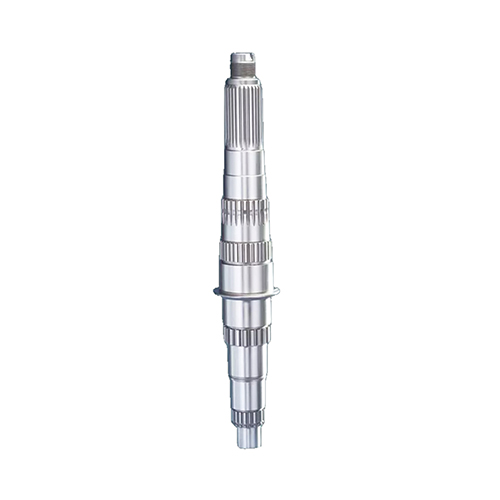
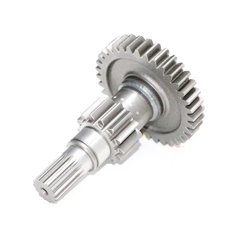
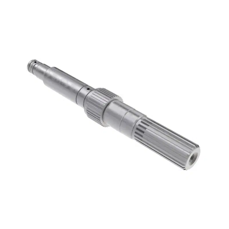
Shaft
Product Details
FAQ
Features & Benefits
-
High-strength shaft materials for torsion & bending
Transmission shafts experience combined torsional and bending stresses from transmitted torque and gear or chain forces. DD Gear typically uses alloy steels such as 42CrMo4 / AISI 4140 / 40Cr and carburizing grades like 20CrMo, which are commonly selected for heavily loaded shafts and gears due to their high strength and good response to heat treatment. -
Tailored heat treatment for core toughness & surface hardness
Through-hardening (quench & temper), localized induction hardening, carburizing or nitriding can be applied where needed: tough cores for bending, hardened surfaces at bearing seats, splines and gear teeth for wear and fatigue resistance. -
Precision fits and runout control
Bearing journals, seal diameters and coupling seats are machined to tolerance classes derived from ISO 286 shaft fits to achieve the required clearances or interference fits for bearings and couplings. This helps maintain low vibration, controlled bearing preload and consistent alignment with mating gears. -
Integrated gear-shaft solutions
For many applications, DD Gear manufactures gear shafts with integral spur or helical gears. Integrating the gear and shaft can reduce interfaces, improve concentricity and runout, and simplify assembly compared with separate parts. -
Small-module precision for compact drives
Combining shaft machining and small-module gear grinding capabilities, DD Gear supports compact EV reduction drives, robot joints and AGV axles where space is tight but accuracy and durability requirements are high. -
Prototype to series production
We support early-stage designs with small prototype batches (including alternative materials or heat treatments), then stabilize the process for series production with defined control plans and traceability.
Technical Specifications
Final values will be defined according to your drawings and performance requirements.
| Item | Typical Option |
| Gear Type | Solid or hollow shafts (where weight and stiffness optimization is required) |
| Material | 42CrMo4 / AISI 4140 / SCM440, 40Cr and other quenched and tempered steels; 20CrMo and other carburizing steels; other alloy steels and stainless steels are selected according to application requirements |
| Heat Treatment |
Normalizing, quenching and tempering (Q&T), induction hardening, overall or partial carburizing, nitriding, etc., depending on the torque, lifespan, and surface hardness targets |
| Surface Hardness | The shaft body is typically tempered to approximately 28–40 HRC; the gear teeth or locally hardened areas can reach 58–62 HRC or as per the drawings |
| Surface finish | Journal and seal surface Ra is typically ≤ 0.8–1.6 μm; tooth surface and spline surface are controlled according to noise and life requirements. |
Applications
Transmission and gear shafts from DD Gear can be found in a wide range of driveline and machinery applications:
-
EV drive units & e-axles – Motor shafts, intermediate shafts and output shafts connecting e-motors, reduction gears and differential units.
-
Truck & bus gearboxes – Input shafts, main shafts and countershafts carrying multiple gears, designed for high torque and long service life.
-
Agricultural and construction machinery – PTO shafts, gearbox shafts and axles in tractors, harvesters, wheel loaders and other off-highway equipment.
-
Industrial gearboxes & gearmotors – Parallel-shaft and right-angle gear units for conveyors, mixers, pumps and compressors.
-
Robotics & AGVs – Compact shafts and gear shafts for robot joints, wheel drives and lifting mechanisms in AGVs and automated systems.
-
Machine tools & equipment – Spindle-like shafts and precision support shafts in CNC equipment, packaging lines and textile machines.
Gear Manufacturing Process
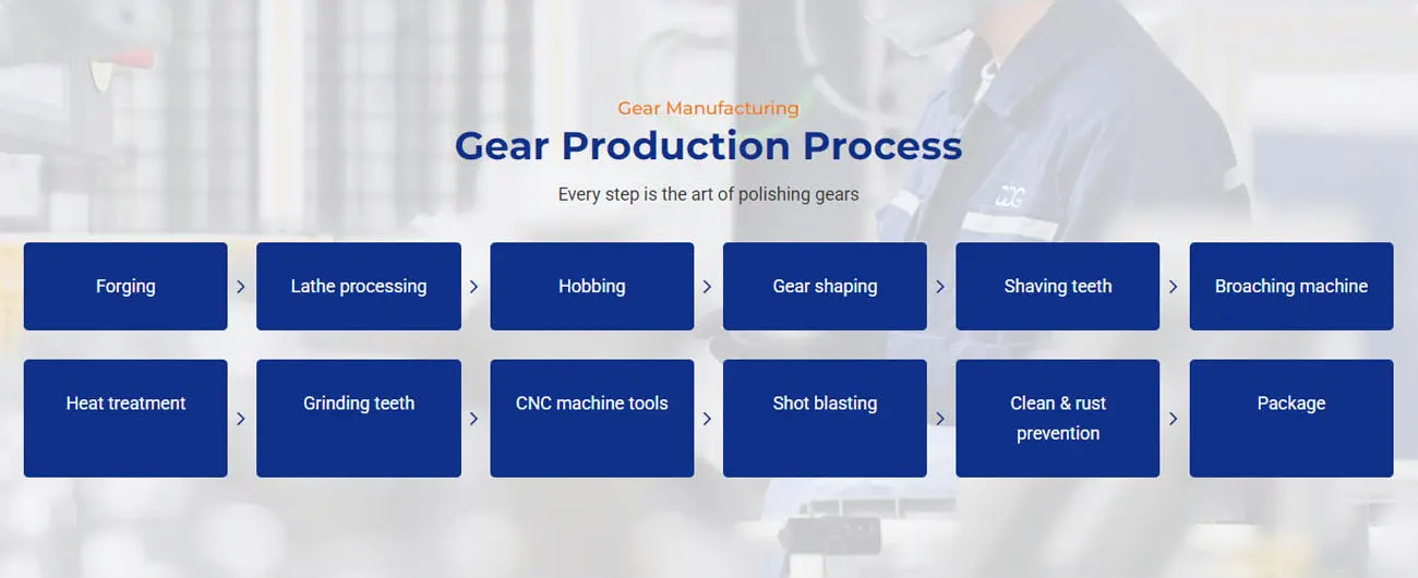
Every custom shaft is produced under a controlled gear manufacturing route designed for precision and durability. A typical process flow is:
-
Forging or bar cutting of shaft blanks
-
Lathe machining of shaft diameters and reference surfaces
-
Hobbing or shaping of gear teeth
-
Drilling, milling, and other CNC machining operations
-
Heat treatment (such as carburizing, quenching, tempering, nitriding)
-
Shot blasting and stress relief as required
-
Finish machining and grinding of journals and critical surfaces
-
Gear grinding (profile or worm grinding) where accuracy demands it
-
Cleaning and rust prevention treatment
-
Final inspection and packaging for shipment
Precision Gear Customization Process
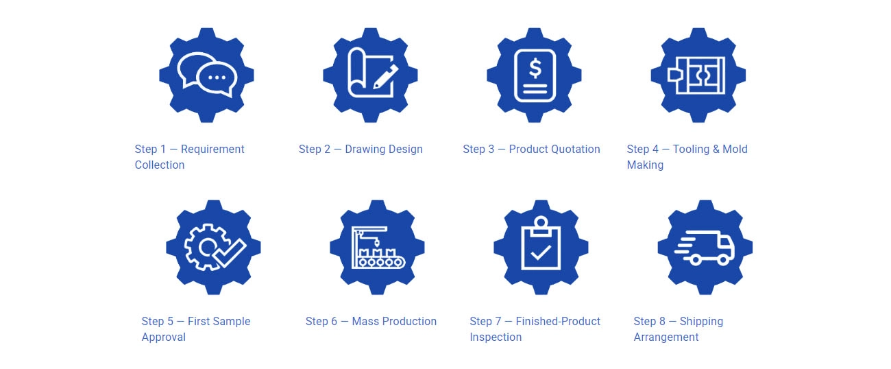
DD Gear follows a clear, eight-step customization process:
Step 1 – Requirement Collection
Customers provide design requirements, 2D drawings, 3D models, or physical samples, together with basic duty cycle information (torque, speed, life, installation).
Step 2 – Drawing Design & Optimization
Based on the provided drawings or samples, DD Gear prepares or optimizes detailed manufacturing drawings and shares them with the customer for confirmation.
Step 3 – Quotation
After the drawings and technical points are confirmed, we issue a precise quotation covering tooling, piece price, lead time, and quality requirements.
Step 4 – Tooling & Fixture Preparation
Once the price is confirmed, we arrange tooling and fixture production. Any tooling cost is agreed with the customer in advance and can be offset or refunded after mass orders, according to the commercial agreement.
Step 5 – First Sample Approval
After tooling and fixtures are ready, we manufacture the first sample batch—typically within about 30 days—and ship it to the customer for testing.The customer inspects and validates the samples in their gearbox or test bench and provides feedback on dimensions, performance, and any required adjustments.
Step 6 – Mass Production
When the sample is approved, we start mass production according to the agreed production plan and quality standards.
Step 7 – Finished Product Inspection
After production, we inspect hardness, dimensions, runout, tooth accuracy, and other critical characteristics to ensure full compliance with the drawing and standards.
Step 8 – Shipping Arrangement
Once inspection is passed and shipment is approved by the customer, we arrange booking, packaging, and delivery to the specified destination.
Quality Assurance & Inspection
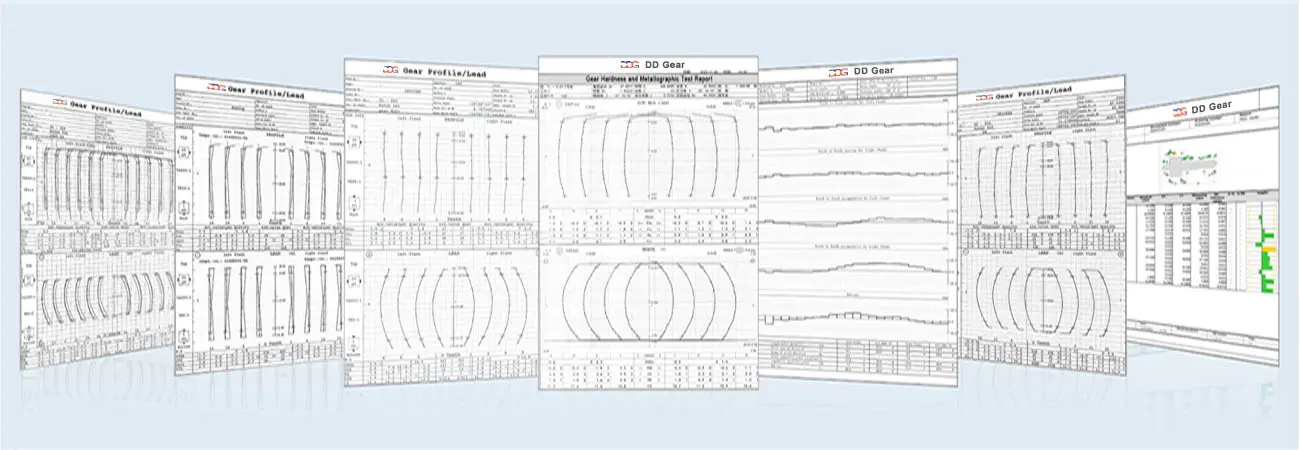
DD Gear applies the same quality philosophy to all precision gears:
-
Quality management systems based on ISO 9001 and IATF 16949
-
Process control from incoming material to final inspection, including:
-
Material certification and chemical composition checks
-
Hardness and case depth verification after heat treatment
-
Gear measurement for profile, lead, pitch, and runout
-
Surface roughness testing on gear flanks and journals
-
Dimensional inspection with calibrated gauges and CMMs
-
-
Traceability for each batch with inspection records and reports
- Optional documentation such as PPAP/FAIR packs on request
Packaging
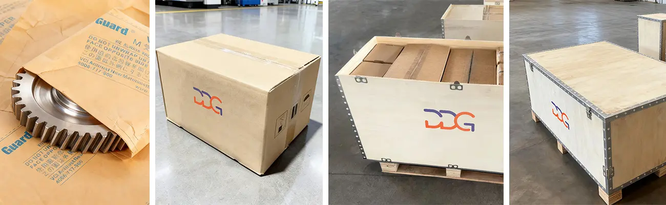
Usage & Installation Notes
-
Ensure proper alignment and support between bearings to avoid excessive bending deflection, which can accelerate fatigue and increase vibration.
-
Follow the specified fits for bearing and coupling seats; forcing parts onto incorrect fits can damage surfaces or alter preload.
-
Avoid sharp damage or nicks on fillets, keyways and splines; these can act as stress raisers and reduce fatigue life.
-
Use the recommended lubricant type and viscosity in bearings and gear meshes; poor lubrication can increase temperature and shorten shaft and bearing life.
-
During maintenance, monitor noise, vibration and bearing temperature; unusual changes can indicate misalignment, imbalance or shaft damage that should be investigated before failure.
Company Strength – DD Gear
-
Specialized in small module, high-precision gears and shafts for EVs, humanoid robots, AGVs, and intelligent automation.
-
Integrated manufacturing from forging and machining to heat treatment and gear grinding.
-
Quality systems aligned with automotive standards, with experience supporting OEM and Tier 1 projects.
-
Engineering support covering concept feasibility, DFM reviews, and failure analysis feedback.
-
Global export capability with experience serving customers in multiple countries.
Q1: What information do you need for a shaft or gear-shaft quotation?
We normally need 2D drawings (PDF) and preferably 3D models; shaft type (solid/hollow, gear shaft or plain); material and heat treatment; torque and speed range; support arrangement (bearing positions and loads); life targets; and expected annual volume.
Q2: Can you help optimize the shaft design for fatigue and deflection?
Yes. Shaft design is driven by torque, bending moments, stress concentrations and deflection / critical speed considerations. Based on your constraints, we can review fillet radii, step transitions, gear and bearing positions and material/heat-treatment choices and provide manufacturability and durability feedback.
Q3: Do you supply shafts with integral gears and splines?
Yes. DD Gear frequently produces gear shafts with integrated spur or helical gears and spline shafts. This reduces assembly steps and can improve runout and alignment versus separate gear and shaft parts.
Q4: How are fits and tolerances defined on shaft journals?
Fits between shafts and bearings or hubs are usually based on ISO 286 tolerance grades and fit types (e.g., clearance, transition or interference fits). We agree specific tolerance classes with you for each journal according to function and assembly method.
Q5: What maximum size of shaft can you handle?
Typical length and diameter limits depend on machine envelope and process route. We will confirm feasible max dimensions when we review your drawings and volumes.
Reliable precision gears for robotics, automotive, and beyond.
Custom Gears for Sliding, Swing & Industrial Doors | DD Gear
Automatic Door Gear from DD Gear is a range of custom-designed, small- to medium-module gears and shafts used in automatic sliding doors, swing doors, revolving doors and industrial doors (sectional, rolling, high-speed doors). In these systems, compact electric motors drive gearboxes and gear trains that must deliver high starting torque, smooth motion and very low noise while opening and closing heavy door leaves hundreds or thousands of times per day. Typical automatic door operators use one or more stages of spur and helical gears in combination with worm gears or bevel gears. Spur gears provide simple, efficient torque transfer for intermediate stages. Helical gears, with their angled teeth and higher contact ratio, help achieve quieter and smoother running, which is critical in hotels, hospitals, offices and residential buildings. Worm gears are often used for high reduction ratios and self-locking behavior, improving safety when the door is at rest and reducing backdrive from wind loads or manual pushing. In some operators, bevel gears change shaft direction between the motor, transmission and drive shaft or belt/chain. DD Gear manufactures Automatic Door Gears strictly on a custom, build-to-print basis. Using customer drawings or validated samples, we supply spur and helical pinions and gears, worm gears and worm wheels, bevel gears, gear shafts and related components for door operators. Through appropriate alloy steels, surface treatments, controlled heat treatment and precision machining, DD Gear helps door-operator OEMs and system integrators build drives that provide quiet operation, long life and reliable performance in entrances exposed to dust, temperature changes and frequent cycling.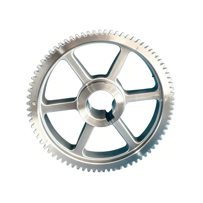
Custom Precision Gears for Electric Wheelchair | DD Gear
Electric Wheelchair Gear from DD Gear covers a family of small-module, custom-designed gears and shafts used in electric wheelchairs, powered mobility scooters and related assistive devices. In these products, compact electric motors drive wheel-side or centrally mounted gearboxes that must deliver high torque at very low vehicle speed, provide smooth, gentle acceleration and braking, and work reliably for years in both indoor and outdoor environments. Typical electric wheelchairs use a single-speed reduction between the high-speed motor and the drive wheel. This reduction is often realized by a worm gear stage, a spur/helical reduction stage, or a planetary gear set integrated into a wheel-side gearbox. Worm gears are commonly used because they can offer high reduction ratios and inherent self-locking behavior in many designs, helping the chair hold position on slopes when the motor is not powered. Spur and helical gears are used in intermediate stages or in designs where efficiency and low noise are prioritized. Planetary gear trains may be used when high torque density and compact packaging are critical, especially in wheel modules. DD Gear manufactures Electric Wheelchair Gears strictly on a custom, build-to-print basis. Based on customer drawings or validated samples, we supply worm gears and worm wheels, spur and helical gears, planetary gear components (sun, planet, ring), gear shafts and wheel-drive gear elements. Using case-hardening steels, controlled heat treatment and small-module precision machining or grinding, DD Gear helps mobility OEMs and system suppliers design drivetrains that offer quiet operation, safe holding behavior, good efficiency and long service life, enhancing comfort and confidence for end users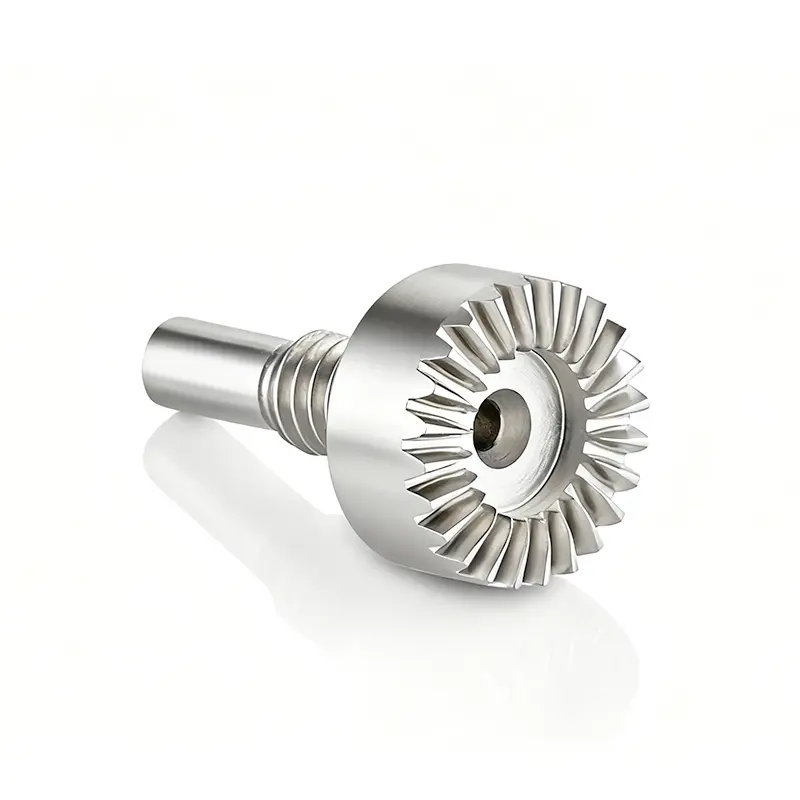
Custom Precision Gears for Surgical Robotics | DD Gear
Surgical Robot Gear from DD Gear covers a family of small-module, high-precision gears and shafts used in surgical robots, robotic-assisted surgical systems and related medical robotic platforms. In these applications, compact actuators drive robotic arms, wrists, end effectors and instrument modules that must deliver micron-level positioning, smooth motion and highly repeatable force control, often in minimally invasive procedures around critical anatomy. To achieve this, surgical robots commonly use spur and helical gears, planetary gear sets and gears integrated with harmonic or other precision reducers inside joint and instrument actuators. These gear stages must work with high-resolution encoders and advanced control algorithms, providing low backlash, high torsional stiffness and consistent friction characteristics across the full range of motion. At the same time, many components operate near the sterile field and must tolerate frequent cleaning and sterilization cycles, use biocompatible or low-outgassing materials and lubricants, and minimize particle generation. DD Gear manufactures Surgical Robot Gears strictly on a custom, build-to-print basis. Based on your drawings or validated samples, we supply spur, helical and bevel gears, planetary components (sun/planet/ring), gear shafts, small-module pinions and interface gears for precision reducers, using carefully selected alloy steels, stainless steels and, where specified, non-magnetic or corrosion-resistant materials. With controlled heat treatment, precision machining and (when required) ground tooth flanks, DD Gear supports surgical robot OEMs and system suppliers in building actuators that deliver precise, smooth and reliable motion, while supporting cleaning and sterilization concepts defined at the system level.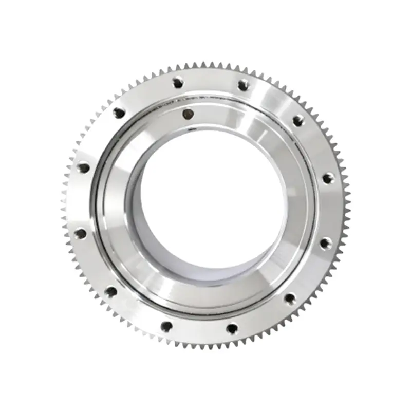
Custom Precision Gears for Automated Guided Vehicles | DD Gear
AGV Gear from DD Gear refers to a range of custom, small-module gears and shafts specifically engineered for Automated Guided Vehicles (AGV) and Autonomous Mobile Robots (AMR) used in warehouses, factories, distribution centers and logistics hubs. In these applications, compact electric motors drive wheel-mounted or centrally mounted gearboxes that must deliver high torque at low travel speed, provide smooth, precise motion control, and withstand continuous start/stop cycles in 24/7 intralogistics operations. Typical AGV drivetrains combine motor + reduction gearbox + drive wheel, often in a wheel hub or wheel-side gearbox design, while steering and lifting functions may use additional gear stages or screw drives. Single- or multi-stage spur and helical gears are common in wheel drives and intermediate stages, while planetary gear sets are widely used where high torque density and compact packaging are required, such as in drive wheels for heavy loads or AGV forklifts. In some architectures, gears are also combined with chain or belt stages to reach the final wheel or mast. Compared with traditional industrial vehicles, AGV/AMR systems place greater emphasis on low noise, smooth operation, positioning accuracy and long maintenance intervals. DD Gear manufactures AGV gears strictly on a custom, build-to-print basis, supplying spur and helical gears, planetary gear components (sun/planet/ring), bevel gears, gear shafts and wheel-drive gear elements based on customer drawings or validated samples. Using case-hardening steels, controlled heat treatment and small-module precision machining or grinding, DD Gear supports AGV and AMR OEMs in building transmissions that provide high efficiency, compact size, low NVH and long service life in demanding indoor and outdoor logistics environments.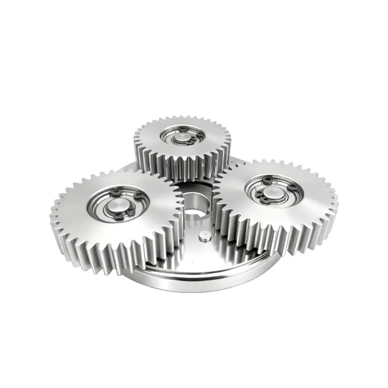
Custom Reduction Gears & Shafts for E-Motorcycle | DD Gear
E-Motorcycle Gear from DD Gear refers to a range of small-module reduction gears and shafts engineered for electric motorcycles, e-scooters, e-mopeds and high-power e-bikes. Instead of multi-speed gearboxes like those used in traditional ICE motorcycles, most electric two-wheelers use a single-speed reduction between the high-speed electric motor and the wheel. This reduction can be realized by hub-motor planetary gear sets, mid-drive spur/helical gear stages, or a combination of gear reduction + chain or belt drive. In hub-motor architectures, a compact planetary gear train is often integrated inside the wheel hub to reduce motor speed and increase wheel torque while keeping unsprung mass and noise under control. In mid-drive or centrally mounted motor layouts, the motor drives an intermediate shaft via spur or helical gears, and torque is then transferred to the rear wheel by a chain or belt. In both cases, the gears must handle high input speeds, frequent acceleration/deceleration, high torque at low road speed, outdoor exposure and strict NVH requirements, all within tight packaging envelopes. DD Gear manufactures E-Motorcycle Gears strictly on a custom, build-to-print basis. Using customer drawings or validated samples, we supply spur and helical pinions and gears, planetary gears (sun/planet/ring), gear shafts and hub-motor gear components. With appropriate case-hardening steels, controlled heat treatment and small-module precision machining or grinding, DD Gear helps electric two-wheeler OEMs and system suppliers build drivetrains that deliver high efficiency, quiet operation, compact packaging and long service life, supporting both urban commuting and higher-performance applications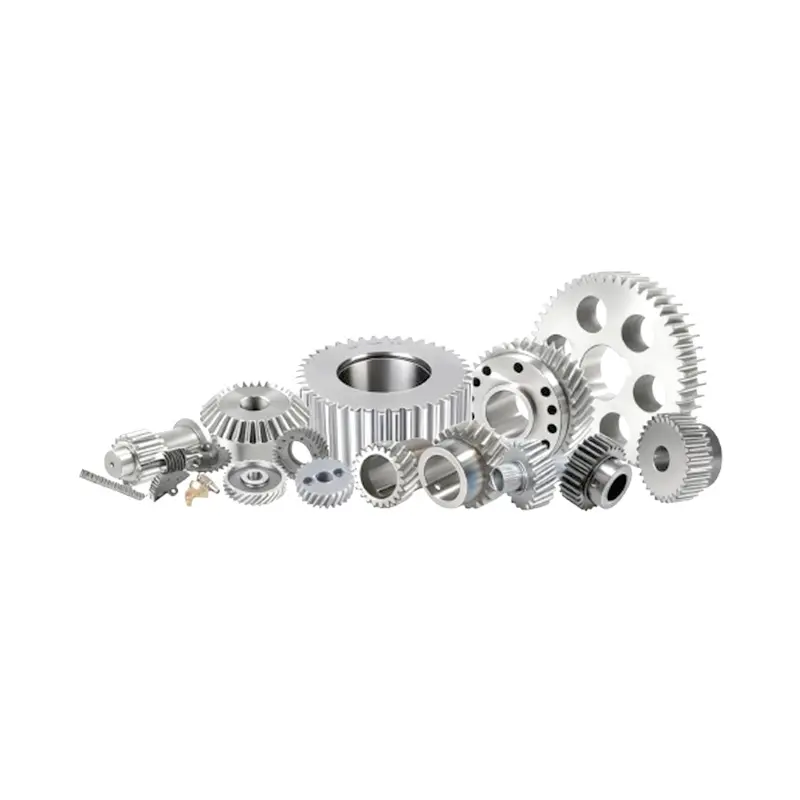
Custom Precision Gears for Packaging Machinery | DD Gear
Packaging Machinery Gear from DD Gear is a family of small- to medium-module, custom-designed gears used in form-fill-seal (FFS) machines, cartoners, case packers, palletizers, labelers and conveyor systems. In modern packaging lines, gears are responsible for coordinating motion between film feed, sealing jaws, product infeed, carton erection, filling, closing and outfeed. They must operate at high speed, often in 24/7 duty, while maintaining precise timing and position to avoid film waste, misaligned seals, product jams and unplanned downtime. Most packaging mechanisms rely on spur and helical gears in gearboxes and timing stages for parallel shafts. Spur gears provide simple, highly efficient torque transmission and are widely used in indexing, feed and cam drives. Helical gears, with their angled teeth and higher contact ratio, offer smoother, quieter running and higher load capacity, which is important in high-speed packaging halls where noise and vibration affect both productivity and operator comfort. In right-angle or compact layouts, bevel gears, worm gears or planetary sets may be used to change direction or achieve higher reduction ratios in a limited envelope. DD Gear manufactures Packaging Machinery Gears strictly on a custom, build-to-print basis. Based on your drawings or validated samples, we supply precision spur, helical, bevel gears, gear shafts and internal gears, using case-hardening steels, nitriding steels, stainless or corrosion-resistant grades, and selected engineering plastics where appropriate. Through controlled heat treatment, finishing and systematic quality control, we help packaging OEMs and retrofitters build gear trains that deliver stable speed ratios, smooth motion, low noise and long service life, even in demanding environments involving dust, humidity or washdownExploring The Science of Precision Gears

How Much Does Gear Microgeometry Modification Add to Manufacturing Cost?
Gear microgeometry modification changes selected areas of a tooth flank without changing the basic gear size. Common examples include tip relief, root relief, lead crowning, edge relief, and twist correction. These modifications can improve tooth contact under defined load, speed, alignment, and temperature conditions. They also add engineering, tooling, machining, heat-treatment, and inspection work. There is no reliable universal percentage for the added cost. The estimate depends on the modification type, module, tooth width, material, heat treatment, accuracy grade, production volume, equipment route, and inspection plan. A prototype with a new tooth form may require considerable setup work. A repeat production order can spread the same engineering and tooling costs across a larger quantity. The most useful way to compare quotations is to ask suppliers to separate design, tooling, processing, inspection, and validation costs. img.Gear tip relief and crowning.webp What Is Gear Microgeometry Modification? Microgeometry refers to small, intentional changes made to the working surface of a gear tooth. These changes may follow the tooth profile direction, the tooth lead direction, or both. The purpose is to manage contact as the gear pair operates under load. Shaft deflection, bearing clearance, housing deformation, thermal expansion, and manufacturing variation can all change the contact pattern. Profile Modification Tip relief removes a controlled amount of material near the tooth tip. Root relief modifies the tooth area near the root. These changes can moderate impact during tooth engagement and reduce sensitivity to changes in load. The relief amount and curve must match the gear speed, torque, mesh stiffness, tooth geometry, and manufacturing process. A generic relief value may not suit every gear pair. Lead Modification Lead crowning places slightly more material near the center of the tooth width. It can help keep contact away from the tooth edges when shaft or housing deflection changes alignment. Edge relief reduces the possibility of concentrated contact at the tooth end. The drawing should identify the modification type, location, amount, tolerance, and measurement method. Twist Correction Twist correction addresses a diagonal contact pattern across the tooth surface. This pattern may result from manufacturing variation, load deformation, or thermal deformation. Twist correction is normally project-specific. A supplier needs the gear geometry, mating gear data, load case, assembly arrangement, and inspection information before quoting the work. Which Cost Elements Does Modification Add? The added cost normally comes from several stages rather than one separate surcharge. Engineering and Drawing Preparation The first stage is requirement review. A supplier may need: A 2D drawing or physical sample Mating gear information Speed and torque Duty cycle Lubrication conditions Backlash requirement Alignment tolerance Operating temperature Required accuracy and surface finish Engineers then define the profile or lead modification, update the drawing, and establish inspection points. A new modification usually requires more engineering time than a repeated production design. Costs can also increase when the mating gear is unavailable or when the load case is incomplete. DD Gear’s customization process includes requirement collection, drawing design and optimization, customer confirmation, and quotation. These activities should be identified clearly in a quotation so the customer can distinguish engineering work from production cost. Tooling and Programming Microgeometry modification may require a special cutter, shaving cutter, grinding wheel, fixture, or CNC tool path. The cost depends on whether existing tooling can produce the required tooth form. Small-batch projects carry a larger share of this setup cost because fewer parts are available to absorb it. Programming can add cost when CNC finishing, skiving, grinding, or specialized correction is required. A new program may need a prove-out run before production. Tool dressing, tool wear, fixture preparation, and setup verification should also be considered when the modification tolerance is tight. Additional Machining and Finishing The process route depends on the gear type, module, material, heat-treatment condition, accuracy grade, and production quantity. DD Gear’s stated machining scope includes: Hobbing Gear shaping Gear shaving Gear grinding Gear skiving CNC machining Milling Broaching Forging Heat treatment Hobbing supports continuous external tooth cutting. Gear shaping can process external gears, internal gears, helical gears, and selected complex profiles. Skiving can be used for selected internal, external, and complex tooth forms when the project suits the available CNC equipment. Shaving is commonly used for semi-finishing and tooth-surface correction on softer tooth surfaces. Grinding is used for hardened gears and precision finishing. CNC machining can support customized finishing or correction steps. Not every project uses every process. The route should be selected from the approved drawing, material condition, accuracy requirement, and production plan. Heat Treatment and Distortion Control Carburizing, nitriding, quenching, tempering, and high-frequency hardening affect hardness, wear resistance, fatigue behavior, and dimensional stability. Heat treatment can also introduce distortion. A hardened gear may require grinding or another finishing process afterward to restore the required tooth geometry. That additional operation adds machine time, inspection, coolant management, and process-control work. Special materials and heat-treatment routes may also extend the prototype schedule. Timing should be confirmed after drawing approval and process review, especially when the modification must be measured after hard finishing. How Much Does Inspection Add? Microgeometry has practical value only when the specified feature can be measured. Inspection cost depends on the characteristics being checked, the required equipment, the sampling plan, and the reporting format. Dimensional and Runout Inspection Routine inspection may include: Outside diameter Bore size Tooth width Tooth thickness Hardness Runout Datum relationships These checks confirm that the gear fits the assembly and that the rotating reference remains stable. The drawing should identify the datums and tolerances used for inspection. Profile, Lead, and Surface Measurement A modified gear may require measurement of: Profile deviation Lead deviation Pitch deviation Tooth thickness Surface roughness Contact pattern Runout Accuracy grade The applicable ISO 1328 cylindrical gear accuracy standard provides terminology and accuracy classifications for cylindrical gears. The project drawing should identify the selected class, measurement conditions, and acceptance limits. The cost of measurement can increase when the customer requests full inspection reports, additional samples, special fixtures, or customer witness inspection. Prototype and Production Inspection The first sample normally receives a fuller inspection and customer review. After approval, production inspection can follow an agreed control plan. DD Gear’s process includes finished-product checks such as hardness, dimensions, and runout. Additional gear-accuracy checks should be determined by the drawing and project requirements. A quotation should state whether inspection reports, sample measurements, contact-pattern checks, and modification iterations are included. img.Gear profile modification test.webp Is Modification More Expensive for Prototypes or Mass Production? Prototype work usually carries a higher engineering and setup cost per part. The supplier may need to: Review the design requirements. Optimize the drawing. Prepare tooling or fixtures. Create the machine program. Produce the first sample. Measure the modified tooth form. Apply customer feedback. Prepare the approved production route. Mass production can reduce the unit impact of tooling and programming because the setup cost is distributed across a larger quantity. Repeat orders may also use an established process route and inspection plan. The unit price still depends on material, heat treatment, cycle time, tool life, packaging, documentation, and inspection requirements. Special materials, internal gears, hardened tooth surfaces, tight accuracy grades, and complex modification curves can increase cost at both prototype and production stages. How Should You Specify Modification on a Gear Drawing? A supplier needs enough information to design and inspect the feature. Include: Gear type Module Tooth count Pressure angle Face width Material Heat treatment Accuracy grade Backlash range Surface-finish requirement Modification type Modification amount or curve Start and end points Reference datum Measurement method Acceptance criteria Also provide mating gear data, speed, torque, load spectrum, alignment tolerance, and operating temperature when the modification depends on system conditions. A statement such as “low-noise modified gear” is difficult to quote and inspect. A drawing should identify the modification and the conditions used to verify it. How Can You Compare Supplier Quotations? Compare the scope behind each price. Ask whether the quotation includes: Drawing optimization Tooth modification design Tooling CNC programming Fixtures Heat treatment Post-treatment grinding First-article inspection Profile and lead measurement Surface-roughness measurement Inspection reports Prototype modification iterations Packaging and traceability Confirm which equipment will be used and which characteristics will be measured. Prototype timing should be stated after drawing confirmation and for a suitable small-module prototype project. Special materials, complex heat treatment, internal gears, or additional inspection requirements may extend the schedule. DD Gear Equipment and Inspection Scope DD Gear focuses on customized small-module high-precision metal gears for medical equipment, robotics, EVs, AGVs, and automation. Its process covers requirement collection, drawing optimization, tooling, first-sample production, customer confirmation, mass production, and finished-product inspection. The machining scope includes hobbing, shaping, shaving, grinding, skiving, CNC machining, milling, broaching, forging, and heat treatment. The selected route depends on the drawing, material, modification type, accuracy, and production conditions. For modified gears, the relevant work may include tip finishing, root-edge repair, crowning, edge finishing, and twist correction. Inspection can cover hardness, dimensions, runout, and gear-accuracy characteristics specified by the project. Manufacturing is described as operating under ISO 9001 / IATF 16949 quality systems where applicable. For more information about its custom gear manufacturing capabilities, visit the DD Gear official website. FAQ Q1: What is included in gear microgeometry modification cost? A: Cost can include engineering review, drawing updates, tooling, programming, additional machining, heat-treatment finishing, inspection, and prototype iteration. Q2: Does tooth crowning always increase gear life? A: Crowning changes the contact pattern and can reduce edge contact under the intended load and alignment conditions. Its effect on service life should be checked through calculation, inspection, and system testing. Q3: Is gear grinding required after microgeometry modification? A: Grinding may be required for hardened gears or for a specified accuracy and surface finish. Softer gears may use hobbing, shaping, shaving, skiving, or CNC finishing. Q4: How should profile relief and lead crowning appear on a gear drawing? A: State the modification type, amount or curve, location, datum, tolerance, and measurement method. Include mating-gear and operating conditions when the modification depends on load or alignment. Q5: What inspection data should a supplier provide for a modified gear? A: Request dimensional and runout results plus the specified profile, lead, pitch, tooth-thickness, hardness, surface-roughness, and contact-pattern data. The report should follow the approved drawing and acceptance plan.

How to Detect and Prevent Gear Grinding Burn
Gear Grinding Burn is a thermally damaged layer created when grinding heat exceeds the gear material and process window. The damage can reduce surface hardness, alter residual stress, create rehardening or softening zones, and increase the risk of pitting or tooth failure. Visual inspection alone cannot establish the condition of a ground flank. A controlled plan combines grinding parameters, coolant delivery, in-process monitoring, and metallurgical inspection. What Gear Grinding Burn Looks Like Burn may appear as a dark band, temper-color change, uneven reflectivity, localized flank staining, or a repeating mark that follows the grinding path. These signs vary with steel grade, heat treatment, coolant, wheel type, and lighting. A part can show no obvious color change and still have a hardness or residual-stress change. On a spur or helical gear, inspect the active flank, tooth tip, root transition, end relief, and lead direction. Record the tooth numbers and clock positions of any marks. A repeatable pattern at the same tooth locations can point to wheel loading, dressing interval, coolant access, or a fixture-related position error. Detection Methods for Gear Grinding Burn Nital etch or approved chemical etch Nital etch can reveal localized changes in the ground surface by producing a contrast between unaffected and thermally altered areas. The method needs a controlled concentration, application time, cleaning step, lighting condition, reference sample, and trained evaluator. The purchase specification should identify the accepted standard and disposition rule. Surface hardness and microhardness Measure surface hardness on representative locations and compare the result with the heat-treatment requirement. A microhardness traverse can show a softened layer or a rehardening zone below the ground surface. Use the test load, indenter, location, and acceptance range stated in the inspection plan. Metallographic section Sectioning provides evidence of white-etching layers, tempered martensite, rehardening, retained austenite changes, and carbide conditions. Use a qualified laboratory procedure and preserve the section location in the report. A metallographic result is especially useful when a Nital indication is disputed or when the gear carries a high fatigue load. Residual-stress and magnetic methods Residual-stress measurement can support a root-cause investigation when the application is sensitive to flank fatigue. Magnetic particle inspection can detect cracks associated with grinding or heat treatment; it does not replace hardness or metallographic checks. Use the method required by the drawing, customer specification, and material condition. Gear geometry and surface finish Measure profile, lead, pitch, radial runout, tooth thickness, and surface roughness after grinding. Burn risk increases when thermal damage combines with geometry errors, excessive waviness, or roughness. The report should link each result to the same datum axis used for production. Engineering Parameters That Control Burn Risk Parameter Typical control record Burn risk signal Corrective action Wheel specification Abrasive, grade, structure, bond, diameter Wheel loads or cuts with high force Select a wheel matched to hardness and stock Dressing Dressing lead, depth, interval, diamond condition Long interval or worn dresser Dress to the validated interval and verify wheel sharpness Infeed and feed rate Radial infeed, axial feed, spark-out High stock removal per pass Reduce infeed, balance passes, and add controlled spark-out Coolant Flow, pressure, concentration, temperature, nozzle aim Interrupted flow or poor flank coverage Restore flow, concentration, filtration, and nozzle alignment Grinding allowance Stock map before finish grinding Local stock peaks or uneven allowance Correct pre-finish stock and review heat-treatment allowance Part rotation and clamping Arbor runout, support, rotation speed Repeating local heat or chatter Correct workholding and verify free-state runout In-process monitoring Power, acoustic emission, temperature trend Rising power or abnormal signal Stop the batch, inspect the wheel, coolant, and part Post-grind inspection Nital, hardness, roughness, gear geometry Indication or hardness shift Segregate, investigate, and approve disposition The values in this table define control categories. A qualified process engineer should set numeric limits from the wheel maker’s data, gear material, hardness, geometry, stock, and machine capability. How to Prevent Gear Grinding Burn Set the stock and datum before grinding Measure stock at several teeth and clock positions after heat treatment. A stable datum, controlled arbor, and verified runout reduce local overloading. Excessive stock at one flank can force the wheel to remove more material than the validated cycle supports. Match the wheel to the gear condition Wheel selection depends on abrasive type, bond, hardness, contact length, gear size, and required finish. A wheel that stays open and sharp for the selected steel can reduce grinding force. The process sheet should identify wheel preparation and the replacement trigger. Maintain coolant delivery Coolant must reach the active contact zone at a stable flow and concentration. Check nozzle position after wheel changes, verify filtration, and record temperature and concentration. A clean, continuous stream supports heat removal and chip evacuation. Use controlled infeed, feed, and spark-out Set the cycle so each pass removes a controlled amount of stock. Monitor power or acoustic emission where available. A short spark-out can reduce elastic deflection; excessive dwell can add heat. Confirm the balance through a capability trial. Control dressing and wheel loading Wheel loading changes cutting behavior and increases heat. Track dressing interval, dresser wear, dressing depth, and wheel balance. Inspect the wheel after an interrupted cycle or an abnormal power trend. Stabilize workholding and inspection conditions An expanding arbor or fixture can distort a thin-rim gear and change contact conditions. Verify arbor runout, support length, clamping force, part rotation, and release behavior. Inspect critical dimensions in the defined free or clamped state. DD Gear Equipment, Processing Range, and Inspection DD Gear’s public quality-assurance page identifies gear measuring centers, CMMs, noise and vibration testing machines, surface-roughness analysis, profile and lead measurement, SPC, and traceability. These tools support dimensional and performance verification around the grinding process. The public website presents custom spur, helical, bevel, hypoid, worm, sprocket, synchronizer, and gear-shaft products for robotics, EVs, AGVs, medical equipment, and industrial automation. Published case information includes small-module work such as m 0.5-2.0 for medical equipment and m 1.5-3.5 for an EV helical reduction programme, with accuracy targets described by ISO/DIN grades for the relevant project. The exact grinding machine model, wheel envelope, maximum diameter, face width, and production quantity remain drawing-specific quotation items. The technical review confirms these items for each quotation. What to Include in a Burn Investigation Report The report should include the gear drawing revision, material heat, heat-treatment record, pre- and post-grind dimensions, grinding machine and wheel identification, dressing record, coolant data, operator and date, failure photographs, Nital or etch result, hardness data, roughness, gear geometry, crack inspection, and final disposition. Attach a marked photograph that identifies the tooth number, flank, lead direction, and scale. Include raw measurement files or plots from the gear measuring center or CMM. State the datum axis, clamping condition, temperature, calibration status, sampling plan, and acceptance criteria. What to Do When Burn Is Found Pause the affected cycle and segregate the lot. Preserve representative parts in the as-ground condition. Confirm the indication with the approved inspection method. Compare hardness, case depth, roughness, and geometry with the drawing. Review wheel, dressing, coolant, stock, feed, infeed, and fixture records. Run a controlled trial after the cause is corrected. Approve rework only when sufficient stock and material condition remain. Document customer-approved disposition for release, rework, re-heat treatment, or scrap. When Rework or Redesign Is Required Rework may be possible when the burn is shallow, cracks are absent, hardness and case depth remain within specification, and the remaining grinding stock can remove the affected layer while preserving tooth geometry. The supplier should prove the route on a sample and repeat the required inspection. Re-heat treatment requires a separate engineering review because it can change distortion, case depth, hardness, and final stock. It is suitable only when the material, geometry, and customer specification support a validated cycle. Redesign is appropriate when burn repeats after a validated process, the stock allowance is too small for controlled removal, the gear section concentrates heat, or the required accuracy and surface condition cannot be achieved within the current process window. Design changes can include revised stock, a more suitable material or heat treatment, a relief radius, modified tooth micro-geometry, or a different finishing route. Conclusion Gear Grinding Burn is controlled through a linked process: stable post-heat-treatment stock, suitable wheel preparation, continuous coolant, controlled grinding energy, stable workholding, and evidence-based inspection. DD Gear’s published quality system includes gear measurement, CMM inspection, surface-roughness analysis, noise and vibration testing, SPC, and traceability. A burn investigation that combines photographs, raw data, process records, and metallurgical evidence gives the buyer a clear basis for rework, process correction, or redesign. FAQ Can visual inspection detect all Gear Grinding Burn? No. Visual inspection can identify surface color or texture changes, while Nital etch, hardness testing, metallography, and residual-stress methods provide evidence of subsurface or microstructural change. Does a rough surface prove grinding burn? No. Roughness can result from wheel condition, dressing, vibration, or process settings. Confirm burn with the approved chemical etch, hardness, or metallographic method. Which DD Gear inspection tools are relevant? DD Gear publicly identifies gear measuring centers, CMMs, surface-roughness analysis, profile and lead measurement, noise and vibration testing, SPC, and traceability. Can a burned gear be ground again? A second grinding operation can be considered when the affected layer can be removed within the remaining stock and the final tooth geometry, hardness, case depth, and surface condition remain compliant. Which standard should define gear accuracy? The drawing should identify the applicable gear accuracy system, such as ISO 1328 or the customer’s DIN or AGMA requirement, together with the grade, datum, sampling, and acceptance criteria.

EV Reduction Gear Noise Causes and Design Solutions
Gear Noise is a system result. In an EV reduction gearbox, tooth geometry, shaft alignment, bearing stiffness, housing resonance, lubrication, and motor excitation combine into the measured acoustic signature. This case-style guide shows how an engineering team can isolate the dominant source and convert test evidence into design and process actions. An EV reduction gear set can produce a narrow tonal peak during coast or light-load operation. The peak often follows gear mesh frequency and its harmonics. Drivers hear it as a whine that changes with vehicle speed. The engineering response starts with a defined test condition: motor speed, torque, oil temperature, gear ratio, microphone position, order-tracking method, and acceptance limit. The team should record the complete operating map alongside the cabin measurement. A map covering drive, coast, acceleration, deceleration, and temperature separates mesh-related excitation from bearing, inverter, and structural responses. Diagnostic evidence for Gear Noise Order tracking and mesh-frequency analysis Calculate gear mesh frequency from shaft speed and tooth count, then compare it with the order-tracked spectrum. A peak that tracks mesh order points the investigation toward transmission error, tooth spacing, profile deviation, lead deviation, or mesh stiffness variation. Gear measurement and runout Measure profile, lead, pitch, radial runout, tooth thickness, and accumulated pitch deviation on a gear measuring center. Link each result to the production datum and drawing revision. Runout and pitch variation create periodic mesh excitation that can appear as sidebands around the mesh order. Housing and bearing response Use accelerometers on the housing and bearing locations alongside microphones. A strong housing response at the same order as the acoustic peak indicates a structural transfer path. Bearing preload, shaft support stiffness, and alignment influence the transfer path and mesh contact. Contact pattern and loaded transmission error Check contact marking under the defined load, then use loaded transmission-error analysis when available. A concentrated contact pattern, edge contact, or rapid contact migration indicates a geometry or alignment condition that needs correction. Engineering parameter table Investigation item Evidence to record Gear Noise mechanism Design or process action Mesh order Shaft speed, tooth count, order map Periodic transmission-error excitation Review profile and lead modifications Profile deviation Total profile, form, slope, tip relief Entry and exit impact Tune tip relief and profile crowning Lead deviation Total lead, slope, crowning, bias Edge contact and load concentration Correct lead crowning and alignment Pitch variation Single and accumulated pitch data Mesh modulation and sidebands Tighten cutting and grinding capability Runout Radial runout, datum, clock position Once-per-revolution excitation Correct datum, blank, and workholding Contact pattern Loaded mark, flank location, temperature Localized load and stiffness change Adjust center distance, alignment, or micro-geometry Housing response Accelerometer order spectrum, mode data Structural amplification Add stiffness or shift natural frequency Lubrication Oil grade, level, temperature, aeration Friction and churning noise Validate oil and delivery conditions Numeric acceptance limits belong in the customer drawing, test specification, and validated process plan. ISO 1328, DIN, or AGMA accuracy requirements should be named with the grade and measurement conditions. Design solutions that reduce EV Gear Noise Apply controlled micro-geometry Tip relief manages tooth entry and exit impact. Profile crowning distributes load along the involute. Lead crowning reduces edge contact when shaft and housing deflect under torque. Each modification needs a loaded contact and durability check because noise, load capacity, efficiency, and pitting risk are linked. Control transmission error through accuracy Reduce pitch, profile, lead, and runout variation through a capable cutting and grinding route. The process plan should connect machine settings, dressing records, in-process checks, and final gear measurement. A stable process produces a repeatable mesh excitation signature. Align the gearset and support structure Set center distance, shaft parallelism, bearing seats, and housing datums from one controlled reference system. Verify free-state and assembled measurements. A geometry correction cannot compensate for an uncontrolled shaft or housing datum. Tune housing stiffness and modal behavior Use modal testing or finite-element correlation to identify housing modes near mesh harmonics. Rib placement, wall thickness, bearing-seat support, and joint preload can change the transfer path. Validate the modified housing with the same order-tracking test. Validate lubrication and temperature Oil viscosity, level, aeration, and jet position change friction and churning losses. Record oil temperature during acoustic tests. Compare results at the temperature range specified for the vehicle programme. DD Gear manufacturing and inspection contribution DD Gear publishes custom spur, helical, bevel, hypoid, worm, sprocket, synchronizer, and gear-shaft products for EVs, robotics, AGVs, medical equipment, and industrial automation. Its quality-assurance information identifies gear measuring centers, CMMs, profile and lead measurement, surface-roughness analysis, noise and vibration testing, SPC, and product traceability. DD Gear has published an EV helical reduction case with module m 1.5-3.5 and ISO 1328 Grade 4-5 accuracy targets for the relevant project. The exact gear diameter, face width, heat treatment, grinding machine, and noise limit remain drawing- and programme-specific quotation inputs. For a Gear Noise investigation, the supplier package should include the gear drawing revision, material and heat-treatment record, gear measurement plots, contact-pattern evidence, roughness data, noise test setup, and corrective-action history. DD Gear’s quality assurance and EV gear case pages provide public reference points for technical review. Recommended case workflow Freeze the test condition and confirm the acoustic repeatability. Convert motor and shaft speed into gear mesh orders. Compare microphone, housing acceleration, and order-tracking data. Measure profile, lead, pitch, runout, roughness, and tooth thickness. Check contact pattern, bearing support, alignment, oil temperature, and housing modes. Run a controlled design or process change with one variable grouped at a time. Re-test the full operating map and document the accepted configuration. What buyers should request in an RFQ Specify the gear type, module, tooth count, ratio, material, case hardness, accuracy grade, profile and lead modifications, roughness, heat-treatment route, noise test method, microphone or accelerometer locations, operating map, and data format. Request a capability plan that links each critical characteristic to a measurement method and sampling frequency. Conclusion An EV reduction gear noise case becomes manageable when the acoustic peak is connected to mesh order, measured gear geometry, contact behavior, structural response, and lubrication state. Design solutions include controlled micro-geometry, stable pitch and runout, aligned datums, tuned housing stiffness, and validated oil delivery. DD Gear‘s published gear measurement, noise and vibration testing, SPC, and traceability capabilities support a documented engineering route from Gear Noise evidence to production control. FAQ What is the first measurement for EV Gear Noise? Define a repeatable operating condition and run order tracking. The mesh order provides the reference for comparing acoustic and vibration evidence. Can tighter gear accuracy remove all noise? Accuracy controls pitch, profile, lead, and runout variation. Bearing, housing, motor excitation, lubrication, and assembly alignment also influence the final sound level. Which gear data should accompany a noise complaint? Provide the drawing revision, operating condition, order map, microphone and accelerometer data, gear measurement plots, contact pattern, oil temperature, and assembly condition. Does profile relief affect durability? Profile relief changes load entry and exit. Validate noise, contact stress, efficiency, and durability together before releasing a new micro-geometry. Which DD Gear capabilities support an EV gear noise project? DD Gear publicly identifies gear measuring centers, CMMs, profile and lead measurement, surface-roughness analysis, noise and vibration testing, SPC, and traceability.

ISO 1328 Gear Accuracy Grades A Practical Guide for Precision Applications
ISO 1328 Gear Accuracy Grades: A Practical Guide for Precision Applications When a gear drawing calls for an ISO 1328 gear accuracy grade, the requirement covers more than one number. It sets a framework for checking tooth spacing, tooth form, tooth alignment, radial runout, and related transmission errors. The grade helps a buyer and a gear manufacturer use the same language when they discuss quality. The right grade depends on the gear’s size, speed, load, noise target, heat treatment, and finishing process. A small high-speed EV gear may need tighter control of tooth form and lead than a larger, slower industrial gear. This guide explains what ISO 1328 measures, how manufacturing affects the result, and how to write a practical requirement for a precision gear project.The EV precision gear range provides context on the application areas. What ISO 1328 Defines ISO 1328 provides a system for evaluating the accuracy of cylindrical gears. It separates several types of geometric error so a measurement report can show where a gear meets its target and where it needs attention. A gear can have accurate tooth spacing and still show a problem in tooth form. It can also have a good profile but a lead error caused by alignment, cutter setup, heat treatment, or grinding. Looking at the grade alone hides these differences. A useful report links each result to the measurement method, datum, gear size, and inspection condition. The standard is most useful when the drawing and the inspection report use the same terms. Before placing an order, define the applicable ISO 1328 edition, the required grade, the inspection locations, and the acceptance rule for the batch. How ISO 1328 Gear Accuracy Grades Work ISO 1328 grades describe the permitted level of geometric error for a gear. The grade number is one part of the requirement. The actual tolerance also depends on the reference diameter, module, tooth count, face width, and other gear dimensions used by the standard. A smaller permitted error corresponds to a tighter manufacturing requirement. That usually calls for better machine condition, controlled datum surfaces, stable heat treatment, and a finishing process such as grinding or honing. A tighter grade can raise production cost and inspection time, so it should match the function of the gear. Grade Selection Depends on More Than the Number Start with the operating conditions. Record speed, torque, load reversals, duty cycle, service life, lubricant, temperature, and the noise target. Then review the gear geometry, including module, tooth width, pressure angle, helix angle, root fillet, contact ratio, and shaft arrangement. These details affect which errors matter most. At high speed, periodic pitch error and profile variation can increase transmission error and mesh noise. In a narrow gear, lead error can reduce the contact area. In a heavily loaded gear, poor alignment can move the contact pattern toward the tooth edge and raise local stress. The mating gear and the housing also affect the result. Bearing clearance, shaft deflection, center distance, assembly runout, lubrication, and tooth modifications can change the working contact even when a gear passes its shop inspection. ISO 1328 gives a geometric quality framework; it does not replace a complete system validation. Common Accuracy Priorities by Application EV e-axle gears often combine high rotational speed, rapid torque changes, compact packaging, and a quiet vehicle environment. The project may therefore place close limits on profile, lead, pitch variation, runout, and surface finish. The chosen grade should follow the drive unit’s noise, efficiency, durability, and production targets. Robot joint gears and precision reducers also need controlled transmission error and repeatable backlash. Industrial gears may accept a wider geometric tolerance when speed and noise requirements are lower, although heavy loads still require control of tooth contact, lead, and runout. These examples describe selection priorities rather than a universal grade table. The gear designer and supplier should confirm the grade after checking the complete geometry and manufacturing route. The Main Measurement Items An ISO 1328 gear report becomes easier to use when each result is tied to a physical effect in the gear mesh. Tooth Pitch Deviation Pitch deviation describes the spacing error between successive teeth or between a measured tooth and the theoretical position. Accumulated pitch error can produce a repeating change in mesh timing. On a high-speed gear, that change may appear as vibration or gear whine. Check whether the report lists single pitch deviation, cumulative pitch deviation, or both. The drawing should also state the measurement direction and the reference datum so different suppliers produce comparable data. Profile Deviation Profile deviation compares the working tooth curve with the theoretical involute. It can reflect errors in cutting, heat treatment, grinding, tool condition, or the selected profile modification. Profile form error and profile slope error do not have the same effect. A local deviation near the tip may affect entry and exit of contact, while a broader slope error can change load sharing across the tooth. The report should show the evaluation range and any designed tip relief or root relief. Helix Deviation Helix, or lead, deviation describes how the tooth runs across the face width. Lead error can come from machine alignment, part mounting, thermal movement, shaft deflection, or distortion during heat treatment. A gear with excessive lead deviation may carry load on one side of the face. This reduces the effective contact width and can increase edge stress. For helical gears, the drawing should state the helix direction, face width, datum, and lead modification where applicable. Radial Runout Radial runout measures the variation of tooth or pitch-cylinder position as the gear rotates around its datum axis. Runout can result from the bore, reference diameter, clamping method, cutting process, or heat-treatment movement. Runout changes the center distance during rotation and can add to transmission error. Measuring the gear from the same datum used in assembly makes the result more useful than a measurement taken from an unrelated surface. Total Composite Deviation Composite tests evaluate the gear while it meshes with a master gear or a defined reference. They combine several geometric effects into a functional result. This type of test can reveal how the gear behaves in mesh, while single-error measurements help identify the source of a problem. Use composite results with profile, lead, pitch, and runout data. One result should not replace the others when the project requires root-cause analysis or process control. Tooth Thickness and Backlash Tooth thickness controls the working clearance between mating gears. Backlash must allow lubrication, thermal growth, manufacturing variation, and assembly movement. Excessive backlash can increase impact and noise; insufficient backlash can cause binding when temperature or alignment changes. State the tooth-thickness method, measurement location, temperature, and datum. The gear accuracy grade does not by itself define the complete backlash requirement. How Manufacturing Processes Affect Gear Accuracy Gear accuracy develops through the whole process chain. Hobbing, shaping, turning, shaving, grinding, honing, and inspection each influence the final result. Tool wear, machine alignment, fixture repeatability, and datum quality can leave different signatures in the report. The precision gear manufacturing process explains how forming, cutting, heat treatment, grinding, and inspection can be arranged for a project. Heat treatment adds another source of variation. Carburizing and quenching can change tooth size, lead, runout, and profile. Induction hardening concentrates heat in selected zones and requires control of coil position, scanning, and cooling. Nitriding usually causes less thermal distortion, yet the core condition and the thin hardened layer still need verification. Heat Treatment and Grinding Allowance Set the grinding allowance before heat treatment. The allowance must cover expected growth, taper, runout, and tooth-form change without removing the intended case or changing the designed geometry. Fixture design and quench transfer time also affect distortion. A practical process plan connects blank inspection, pre-treatment, machining, heat treatment, grinding, cleaning, and final measurement. Checking hardness alone cannot show whether the gear meets its accuracy requirement. Gear Accuracy After Finishing Final ISO 1328 inspection should take place after the last operation that can change tooth geometry. For a ground gear, that normally means measuring after grinding, deburring, cleaning, and temperature stabilization. Record tooth form, lead, pitch, runout, tooth thickness, surface condition, and the applicable accuracy grade. The report should identify the instrument, calibration status, measurement temperature, datum, evaluation range, and inspection sample. These details let the buyer compare results across batches and investigate a change in the process. How to Specify ISO 1328 on a Gear Drawing A clear drawing gives the supplier enough information to plan production and gives the inspector a defined acceptance rule. Include: The applicable ISO 1328 edition and part. The required accuracy grade. Profile, lead, pitch, and runout limits. Tooth thickness, backlash, or measurement-over-pins requirements. Datums, inspection direction, and evaluation range. Material, heat treatment, hardness, and case-depth requirements. Grinding allowance and final surface condition. Sampling frequency, batch definition, and reporting format. If the gear operates in a sensitive noise application, add the transmission-error, surface-finish, balance, and functional test requirements that the system team has approved. These requirements sit alongside the ISO 1328 grade. How to Choose the Right ISO 1328 Gear Grade Use a staged review rather than selecting a grade from a catalog alone. First, define speed, torque, life, temperature, lubrication, and noise limits. Next, confirm gear geometry, shaft features, packaging, and load distribution. Then compare candidate material and treatment routes, such as carburized 20CrMo, induction-hardened 42CrMo, or nitrided 38CrMoAl when those routes suit the design. Review the expected contact stress, tooth-root stress, case depth, distortion, machining stock, and finishing capability. Ask the supplier which cutting and finishing operations can hold the proposed grade and how the supplier will measure it. Validate samples with dimensional, accuracy, hardness, case-depth, surface, and functional checks before releasing a mass-production process. DD Gear’s Approach to Precision Gear Manufacturing DD Gear produces small-module, precision metal gears for EVs, robotics, AGVs, and intelligent automation. Its work can cover input shaft gears, parking-end gears, main reduction gears, and drive motor shafts. These applications require the gear drawing, material, heat treatment, tooth geometry, accuracy target, and inspection method to work as one specification. FAQ Q1: What does an ISO 1328 gear accuracy grade mean? A: It defines a permitted level of geometric error for a cylindrical gear. The grade works with the gear’s size, module, tooth width, and specified measurement method. Q2: Which ISO 1328 gear grade is suitable for EV e-axle gears? A: The suitable grade depends on speed, torque, noise target, gear size, heat treatment, and finishing process. Select it after reviewing the complete drive-unit requirements rather than using one grade for every EV gear. Q3: Does a higher ISO 1328 gear grade always reduce noise? A: A tighter geometric grade can reduce one source of transmission error. Noise also depends on tooth microgeometry, surface finish, alignment, bearings, housing stiffness, lubrication, and dynamic balance. Q4: How does heat treatment affect ISO 1328 gear accuracy? A: Heating and quenching can change tooth size, profile, lead, runout, and alignment. The process plan should include distortion allowance, fixturing, machining stock, and post-treatment finishing. Q5: What should a buyer include in an ISO 1328 gear drawing? A: Include the ISO 1328 edition and grade, gear dimensions, profile and lead limits, pitch and runout requirements, tooth thickness or backlash, datum, material, heat treatment, hardness, finishing allowance, inspection method, and batch acceptance rule.

What to Do When Gear Distortion After Heat Treatment Is Excessive
Excessive gear distortion after heat treatment can change bore size, tooth position, face runout, profile, lead, and radial runout. The recovery decision should be based on measured geometry, material condition, remaining machining stock, and the drawing’s functional datums. A controlled investigation separates heat-treatment movement from errors introduced during machining, fixturing, grinding, or measurement. This guide gives a practical response for custom gears, carburized gears, induction-hardened gears, and other precision gear parts. It is intended for engineering, quality, and sourcing teams reviewing a nonconforming gear batch. First response: contain and preserve evidence Quarantine the affected lot and identify the material heat, furnace load, heat-treatment recipe, machining route, and operator records. Do not straighten, grind, or rework the parts before the baseline condition is documented. Mark each sample so measurements can be traced to a specific blank, furnace position, and inspection report. Keep one representative part in the as-treated condition. Photograph the bore, faces, outside diameter, and tooth flanks under consistent lighting. A failure photo should show the feature and include a scale or fixture reference. Record whether the distortion is uniform around the circumference or concentrated at certain clock positions. Detection data to collect Measure the part at a controlled temperature, preferably 20 °C when the drawing or inspection standard specifies it. Use calibrated equipment and state the datum axis, clamping condition, probe strategy, and software revision in the report. Measurement item Recommended data What it helps identify Decision use Bore diameter and roundness Minimum, maximum, average, lobing plot Quench movement, carburizing growth, fixture loading Confirms whether boring or grinding stock remains Bore-to-face runout Total indicator reading at defined face Face movement, uneven support, machining datum error Tests datum suitability for arbor or inspection Outside diameter and face runout Clock-position values and polar plot Rim growth, axial bow, asymmetric cooling Separates global movement from local distortion Tooth radial runout Composite or single-flank runout by tooth Tooth-center movement relative to datum axis Indicates whether tooth grinding can restore the axis Profile and lead deviations Traces at specified teeth and flank positions Local tooth bending, stock variation, grinding allowance Establishes whether flanks have enough correction stock Hardness and case depth Surface hardness, core hardness, case-depth result Under- or over-hardening, abnormal transformation Determines if re-heat treatment is technically viable Crack and burn inspection MPI or other approved method, plus visual record Quench cracks, grinding cracks, thermal damage Determines whether the part is repairable Record pre-heat-treatment values beside post-treatment values. This comparison shows the movement vector instead of treating the final deviation as a single unexplained number. A practical troubleshooting flow Use the following sequence before approving a corrective action: 1.Confirm the measurement. Recheck the part on a calibrated gear measuring center, CMM, or approved gauge. Repeat the measurement with a second qualified operator when the result is close to the acceptance limit. 2. Check the datum chain. Compare the inspection datum with the machining and heat-treatment fixture datums. A fixture axis that differs from the drawing datum can appear as heat-treatment distortion. 3. Map the distortion. Plot bore, face, outside diameter, and tooth runout at clock positions. A consistent sinusoidal pattern often points to support or fixturing; a localized peak can indicate uneven heating, quench access, or a material issue. 4. Review process records. Check furnace temperature uniformity, atmosphere or carbon potential, transfer time, agitation, quenchant condition, load spacing, tempering cycle, and actual part orientation. 5. Check material condition.Verify material certification, grain flow where applicable, prior normalizing or annealing, hardness, and case-depth results. 6. Calculate recoverable stock. Compare measured deviation with the remaining bore and tooth-grinding allowance. Include fixture runout, dressing variation, and the required final relationship between bore and teeth. 7. Run a controlled trial.Use one or two parts for stress relief, straightening, rough grinding, or an approved re-machining route. Inspect after each operation and update the capability estimate. 8. Disposition the lot. Release, rework, reprocess, redesign, or scrap the lot using documented engineering and customer approval. Common causes and corresponding solutions Uneven heating or quenching Large temperature gradients, poor load spacing, inconsistent agitation, or a quenchant with changed viscosity can produce nonuniform transformation. Review furnace surveys, load maps, quenchant maintenance, transfer time, and part orientation. Corrective actions may include a revised basket, controlled spacing, a different agitation setting, a quenchant replacement, or a validated recipe window. Insufficient pre-heat-treatment stock If the blank or tooth flanks were machined too close to final size, normal movement may exceed the available grinding allowance. Confirm stock at multiple clock positions rather than checking one diameter. If stock is insufficient, limited re-machining may be possible on nonfunctional surfaces; otherwise, the part may require a new blank or a revised allowance. Residual stress from prior machining Heavy interrupted cuts, sharp tool wear, poor support, or an unbalanced material-removal pattern can leave stress that releases during hardening. Review roughing sequence, tool condition, clamping force, and intermediate stress-relief practice. A revised route may use balanced stock removal, a stress-relief cycle, and a longer stabilization interval before tooth cutting. Incorrect material or prior heat-treatment condition Material mix-up, segregation, an unsuitable steel grade, or incomplete annealing can change transformation behavior. Hold the lot, verify the mill certificate and positive material identification, and compare hardness and metallographic results with the specification. Re-heat treatment should proceed only after a qualified review confirms that the material condition and case requirements can be met. Fixture or support deformation A mandrel, plug, basket, or face support can constrain the part during heating or quenching. Evidence includes distortion that follows support points or repeats at the same clock positions. Inspect fixture runout, contact marks, wear, clearance, and thermal expansion. Modify the support scheme and validate it with a pilot load. Excessive grinding heat after treatment Grinding burn or thermal stress can add distortion after the hardening cycle. Check coolant delivery, wheel specification, dressing interval, infeed, feed rate, spark-out, and part rotation. Use approved burn inspection and hardness checks before deciding that the heat-treatment process is the primary cause. When re-machining is appropriate Re-machining can be considered when the material, hardness, case depth, and crack condition are acceptable and sufficient stock remains on the controlled features. The supplier should issue a revised process route that identifies the new datum, roughing allowance, finish allowance, clamping method, and intermediate inspections. Typical recovery routes include rough bore grinding followed by tooth grinding, controlled face correction, or a final bore operation after tooth finishing. Each route must preserve the required tooth-to-bore relationship. A trial part should demonstrate the result before the complete lot is processed. Re-machining is generally unsuitable when the case has been ground through, cracks are present, the bore or teeth are below minimum stock, hardness is outside the specification, or the corrected geometry would move a functional feature outside its drawing envelope. When redesign or a new part is needed Request a design review when the same distortion pattern repeats after a validated process, when the wall section is too thin for the specified case depth, or when the drawing allows less correction than the material and heat-treatment route can reliably provide. Design options may include a more stable steel grade, a modified rim or web geometry, a larger relief radius, a different datum strategy, a revised case-depth range, or additional stock for post-treatment grinding. Redesign should be supported by capability data, not by a single outlier. The review should compare the required gear accuracy, bore-to-tooth runout, load, noise, service temperature, heat-treatment method, and target production volume. Any drawing change requires customer approval and a first-article inspection plan. Inspection and reporting expectations The nonconformance report should attach failure photos, raw measurement data, the pre- and post-treatment comparison, process records, material and hardness results, the troubleshooting flow, and the proposed disposition. State the measurement equipment, calibration status, reference axis, sampling plan, and acceptance criteria. ISO 1328-1 defines a classification system for flank tolerance of cylindrical involute gears. The applicable edition and accuracy grade should appear on the drawing or inspection plan. Heat-treatment controls and metallurgical interpretation should follow the applicable customer specification and qualified process standard. DD Gear describes its quality-assurance process and manufacturing capabilities for custom gears. Its cooperation process can be used to organize drawing review, sample development, corrective action, and production documentation. Conclusion When gear distortion after heat treatment is excessive, contain the lot, preserve the as-treated evidence, verify the datum, map the geometry, and compare the deviation with available correction stock. Re-machining is appropriate only when the material condition, case, cracks, and remaining stock support a controlled recovery route. Repeated distortion, inadequate section design, or an impossible tolerance relationship indicates a need for redesign or a new part. FAQ Can a distorted gear always be straightened? No. Straightening depends on material condition, hardness, crack risk, geometry, and the customer’s process specification. It requires a validated method and post-process inspection. Which data should be measured first? Start with bore size and form, bore-to-face runout, face runout, outside diameter, and tooth radial runout. Then add profile, lead, hardness, case depth, and crack results. How much grinding stock is enough for recovery? The required stock depends on measured distortion, part variation, fixture error, wheel behavior, and the final drawing tolerances. Use a capability study rather than a generic allowance. When should a supplier re-heat-treat a gear? Re-heat treatment requires engineering approval after reviewing hardness, case depth, alloy, distortion risk, and crack risk. It is not a default response to dimensional nonconformance. What should a corrective-action report contain? Include failure photos, detection data, process records, root-cause evidence, containment, corrective actions, rework limits, verification results, and the final disposition decision.

How to Select Carburized Case Depth for a Fine-Pitch Gear
A Fine-Pitch Gear needs a carburized case that supports the contact zone and tooth root while preserving a tough core. The drawing should define the depth by a recognized measurement method, identify the inspection location, and connect the requirement to material, heat treatment, finishing stock, and load. Module alone provides an initial scale; the final value follows a complete stress and process review. This guide explains the variables engineers should review before releasing a case-depth specification for compact metal gears used in robotics, electric drives, medical equipment, actuators, instruments, and automated machinery. Start with the case-depth definition Carburizing adds carbon to the steel surface. Quenching then forms a hard case around a lower-carbon core. The resulting hardness gradient affects surface fatigue, wear resistance, tooth-root strength, and resistance to subsurface damage. The term “case depth” needs a stated definition. Effective case depth is determined from a microhardness traverse to a specified limiting hardness. Total case depth is determined by the applicable measurement method defined in the relevant standard and represents the depth of the hardened case based on the specified criteria. Therefore, effective and total case depth values should not be treated as the same measurement. According to ISO 18203:2026, the depth of carburized and hardened cases in steel components is determined using specified measurement methods and evaluation criteria. A purchase drawing should define the applicable standard, case-depth type (effective or total), required depth range, limiting hardness where applicable, test method, inspection location, and acceptance criteria to ensure consistent interpretation between the heat treater and inspector. Scale case depth to the Fine-Pitch Gear tooth The tooth is the relevant section. A depth that is moderate on a large gear can occupy much of the root section on a small-module part. Engineers often begin with a case-depth-to-module relationship, then adjust it for stress, material, geometry, heat-treatment capability, and finishing operations. Research published by Gear Technology reports that the bending strength of case-carburized gears is influenced by the ratio of case depth to gear module. This relationship matters strongly in fine-pitch designs because the tooth tip, root fillet, and remaining core are small. Use the module ratio as a screening tool. A load-capacity calculation and metallurgical review should set the production range. ISO 6336-5:2016 covers material strength and quality considerations used in spur and helical gear load-capacity calculations, including requirements for case-carburized and hardened gears. Match depth to the governing failure mode Case-depth selection starts with the location and type of stress the gear must carry. Contact fatigue at the flank Hertzian contact stress creates a subsurface stress field below the active flank. The hardened zone should extend far enough to support that field under the specified torque, duty cycle, load distribution, and lubrication condition. A shallow hardened zone can place peak shear stress near softer material and increase the risk of case crushing, pitting, or deeper flank damage. Contact calculations should include dynamic load, face-load distribution, surface finish, profile modification, misalignment, temperature, lubricant viscosity, contamination, and expected life. A compact gear with intermittent shock loading may need a different hardness profile from a gear carrying smooth, steady torque. Tooth-root bending The root fillet carries cyclic tensile stress. The case at this location contributes hardness and compressive residual stress, while the core supports the tooth section. Root geometry, rim thickness, notch sensitivity, surface condition, and grinding marks all influence the required balance. A very deep high-carbon layer can reduce the proportion of tough core within a thin tooth. The engineering review should consider root bending strength together with the risk of excessive brittleness, quench cracking, and distortion. Wear, scuffing, and impact Wear and scuffing depend on surface hardness, roughness, sliding, lubricant film, temperature, and material pairing. Case depth supports the surface, while surface carbon, retained austenite, carbide distribution, and final finish affect how the flank behaves. Impact and overload place additional demand on core toughness. The specified steel and heat-treatment cycle should produce a hardness gradient that supports the case through the intended overload condition. Include the steel and core section Steel chemistry controls hardenability, carbon response, retained austenite, grain growth, and the hardness transition from case to core. Two gears with the same module and nominal depth can develop different profiles when they use different alloys or quench conditions. The Fine-Pitch Gear material review should cover: Steel grade and hardenability band Initial microstructure and incoming material condition Surface carbon target and carbon-potential control Carburizing temperature and diffusion schedule Quench method, agitation, and section size Tempering cycle and final surface hardness Core hardness and minimum supporting section Retained austenite, carbide network, and intergranular oxidation limits where required Thin rims, webs, hubs, keyways, and asymmetric features can change heating and cooling behavior. The gear blank design belongs in the case-depth review because the heat-treatment response follows the whole component. Account for grinding and stock removal The drawing should distinguish case depth before and after hard finishing. Gear grinding, gear-flank grinding, flank superfinishing, or other stock-removal operations reduce the finished case. The process route needs enough allowance to achieve the specified depth on the final surface. Grinding also adds thermal and mechanical risk. Excess heat can temper the surface, create tensile residual stress, or produce grinding cracks. Inspection may therefore include surface hardness, microhardness profile, nital etch or another burn-detection method, tooth geometry, and crack detection according to the drawing and application. For a Fine-Pitch Gear, small stock changes represent a larger fraction of the tooth. Heat-treatment distortion can also shift profile, lead, runout, and tooth thickness. The manufacturing plan should link pre-heat geometry, expected growth or shrinkage, grinding stock, and the finished case-depth requirement. Specify where the case depth is measured Carburizing response varies around the tooth. The tip, pitch-line region, root fillet, end face, and masked surfaces can show different carbon diffusion and cooling conditions. A requirement that lists only one depth range leaves the inspection location open to interpretation. Define the location on a Fine-Pitch Gear drawing or inspection plan. Useful details include: Tooth flank, root, or both Distance from the tip, pitch line, or root tangent Mid-face position or a defined distance from the end face Test direction and surface normal Number of samples and sampling frequency Production gear, sacrificial gear, or representative coupon Effective-depth limit hardness and traverse spacing Acceptance rules for surface hardness, core hardness, and microstructure A coupon can confirm furnace conditions and material response. A sectioned gear captures local tooth geometry, section thickness, stock removal, and quench response. Critical programs may use both forms of evidence. Use a drawing-based selection workflow The following sequence keeps the design calculation, heat-treatment route, and inspection record aligned. Review step Engineering input Required output 1. Define duty Torque spectrum, speed, life, overload, temperature, lubrication Design load cases and safety factors 2. Calculate gear stresses Module, tooth count, pressure angle, helix angle, face width, modifications Contact and root stress results 3. Select material Steel grade, hardenability, core section, blank condition Material and core-hardness requirements 4. Set the case range Stress depth, module ratio, root support, process capability Preliminary effective case-depth range 5. Add process allowances Distortion, grinding stock, finishing sequence Pre-finish and finished depth targets 6. Define verification Standard, test location, hardness threshold, sampling Inspection plan and report fields 7. Validate production First article, hardness profile, microstructure, gear geometry Approved process window This workflow produces a traceable specification. Each depth value connects to a stress calculation, material response, manufacturing operation, or inspection result. Common specification errors Using module as the only input Module provides geometric scale. Torque, tooth count, face width, load distribution, service life, steel, core section, and finishing route determine how the case supports the design. Listing depth without a hardness criterion Effective and total case depth use different evaluation criteria. State the applicable measurement standard, case-depth definition, and limiting hardness where required so that test reports describe the same property. Ignoring the root location A flank measurement supports contact-fatigue review. Root bending may require a separate depth and microstructure check at the fillet. Applying the pre-grind result to the finished gear Hard finishing removes material and may alter surface condition. The final acceptance plan should address the finished tooth when the drawing controls delivered performance. Treating the furnace coupon as the complete result Coupons provide useful process evidence. Local tooth geometry and section size affect the production part, so the validation plan should include representative gear sections where risk or customer requirements justify them. DD Gear support for case-depth planning DD Gear produces custom high-precision gears for robotics, EV, AGV, medical equipment, electric tools, and industrial automation projects. Its process planning can connect drawing review, blank preparation, tooth cutting, heat treatment, hard finishing, and final inspection. The company’s quality-assurance process covers incoming material checks, in-process inspection, gear measurement, CMM inspection, surface-roughness analysis, and traceability. For a carburized gear project, the inspection scope can add the hardness traverse, effective case depth, core hardness, microstructure, retained austenite, and crack-detection records required by the drawing. Send the gear drawing, material specification, module, tooth data, load spectrum, heat-treatment requirement, finishing stock, annual quantity, and inspection-document list. DD Gear can review a Fine-Pitch Gear project against its custom gear manufacturing capabilities and prepare a process route for technical discussion. Conclusion Case depth for a Fine-Pitch Gear follows the tooth scale, stress field, failure mode, steel response, core section, heat-treatment process, and finishing allowance. The drawing should state the depth definition, measurement standard, hardness threshold, test location, sampling plan, and finished-part acceptance range. A first-article hardness profile and metallurgical review provide evidence for the selected process window. Share the project data through the DD Gear contact page to review the carburizing, finishing, and inspection route. FAQ What is effective case depth in a carburized gear? Effective case depth is the perpendicular distance from the surface to the point where hardness reaches a specified limiting value. The drawing should identify the governing standard (such as ISO 18203:2026), hardness threshold, test method, and measurement location. Does a smaller module always require a shallower case? Smaller teeth generally use a shallower absolute case because the tooth section is smaller. The final requirement also follows contact stress, root stress, material, core support, life, overload, and finishing stock. Should case depth be checked at the flank or root? The inspection location should match the controlled risk. Flank measurements support contact-fatigue evaluation, while root measurements support bending and fillet assessment. Some projects specify both. How does gear grinding affect case depth? Grinding removes part of the carburized layer. The heat-treatment target should include grinding allowance, and the finished gear should retain the depth and hardness profile stated on the drawing. What data should a supplier receive before quoting carburizing? Provide the drawing revision, module, tooth geometry, steel grade, load and life targets, surface and core hardness, case-depth definition (effective or total), applicable heat-treatment standard (such as ISO 18203:2026), finishing stock, inspection location, sampling plan, and required records.


LOVE TO HEAR FROM YOU GET IN TOUCH!
Please fill out the form below and we will get back to you as soon as possible.