- support@ddgear.com
- North 3F, Building 13-2, Zhixin Park, NO.1099 Xianhua South Street, Wucheng, Jinhua, Zhejiang, China.
Products
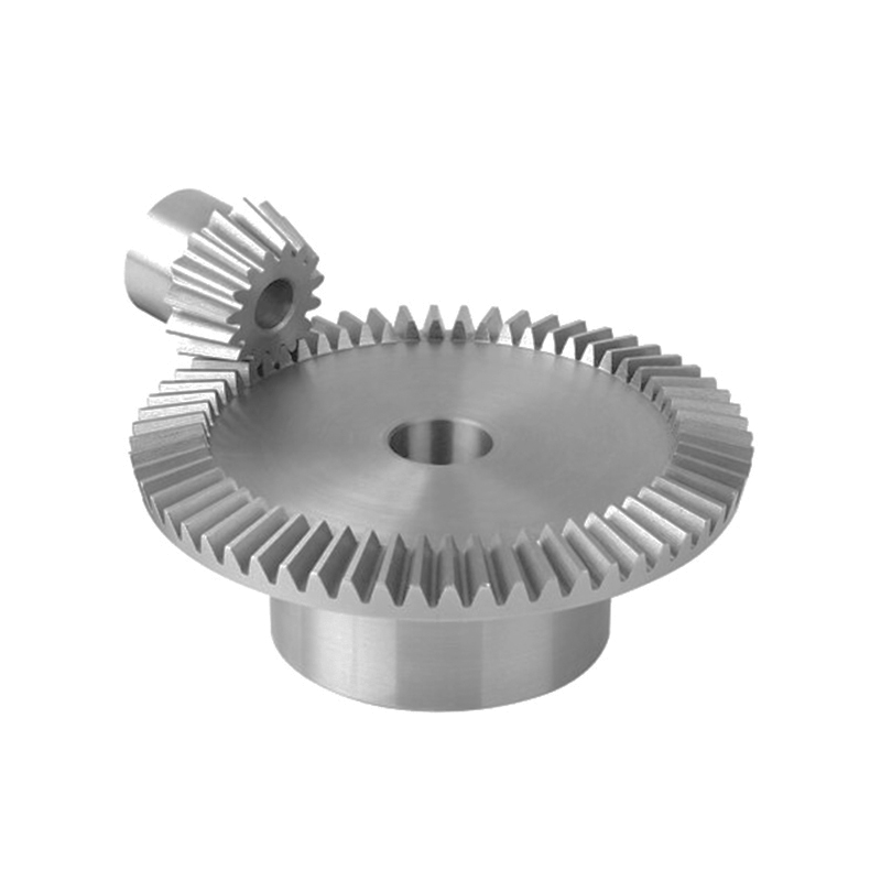
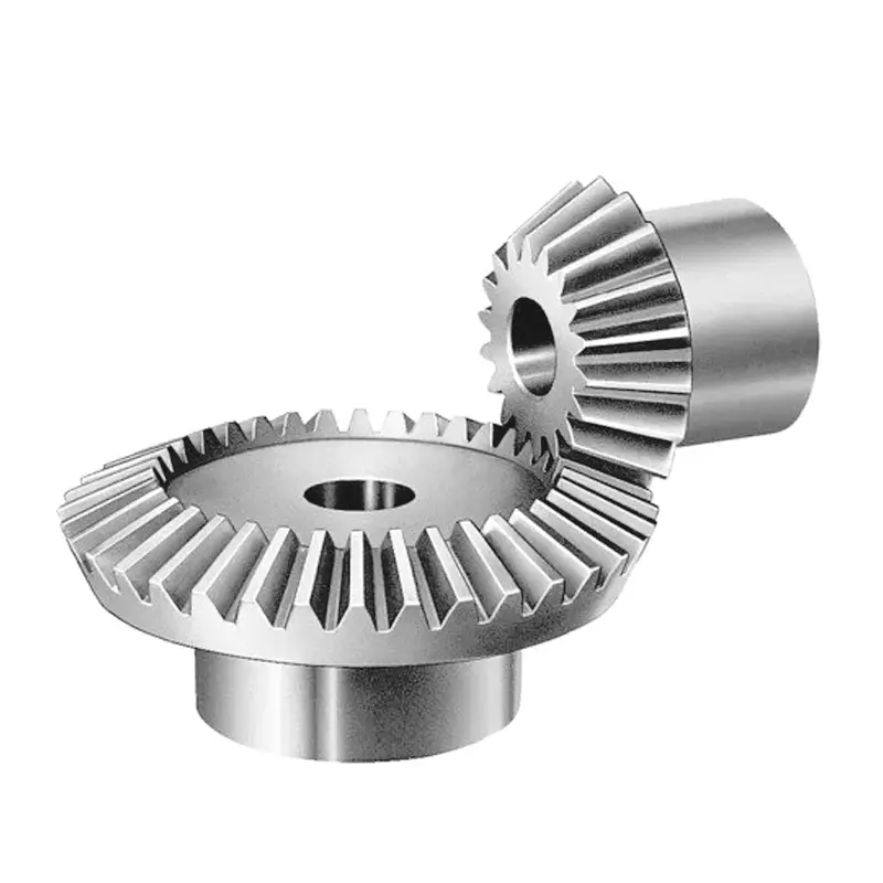
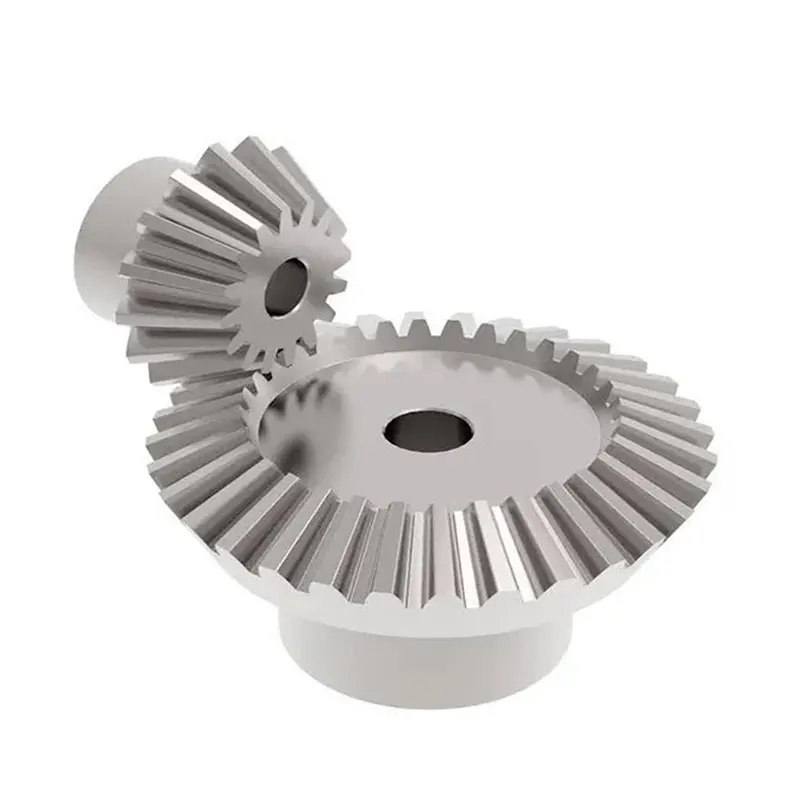
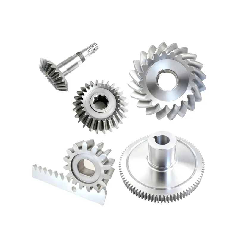
Bevel Gear
Product Details
FAQ
Features & Benefits
-
Angular power transmission in compact layouts
Bevel gears transmit power between intersecting or crossing shafts—often at 90°—enabling compact right-angle gearboxes and differentials that would be difficult to realize with cylindrical gears alone. -
Multiple tooth forms for different requirements
Straight bevel gears are relatively simple and suitable for moderate speeds; spiral bevel gears offer higher contact ratio, higher strength and smoother running; hypoid gears allow shaft offset and are widely used in automotive and off-highway axles. -
High load capacity for driveline applications
Properly designed spiral bevel and hypoid gears can transmit large torques in vehicle differentials, industrial drives and heavy machinery. -
Controlled geometry per international standards
DD Gear designs bevel and hypoid gears with geometry compliant to ISO 23509, which defines terminology and tooth geometry for straight, spiral, zerol and hypoid designs. -
Accuracy based on DIN / ISO bevel gear systems
We align tolerancing with standards such as DIN 3965 and the ISO bevel gear accuracy system referenced in AGMA/ISO documents, ensuring tooth variations and runout are kept within defined grades for stable contact patterns. -
Small-module precision for robotics and EV
Beyond classic automotive differentials, DD Gear focuses on small-module bevel gears for compact robot joints, AGVs, medical and automation equipment, where angular transmission must be precise and space is limited.
Technical Specifications
Final values will be defined according to your drawings and performance requirements.
| Item | Typical Option |
| Gear Type | Straight bevel, spiral bevel, zerol bevel, hypoid gear sets |
| Module (m) | Small- to medium-size bevel gears according to drawing |
| Material | Carburizing alloy steels (such as 16MnCr5, 18CrNiMo, etc.), nitriding steels, and other alloy steels should be selected based on torque and life requirements |
| Heat Treatment |
Carburizing & quenching (commonly used for high-load bevel/hypoid), nitriding, quench-and-temper, induction hardening, etc., combined with gear grinding to improve performance |
| Surface Hardness | Typically 58–62 HRC on carburized teeth or per drawing; core toughness controlled according to bending fatigue requirements |
| Surface Finish | Ground or lapped flanks to achieve defined roughness and contact pattern requirements |
| Accuracy | Bevel/hypoid gear accuracy per ISO/DIN system (such as DIN 3965, ISO bevel gear accuracy tables, published by AGMA/ISO), with specific grades defined in consultation with the customer. |
Applications
Bevel and hypoid gears from DD Gear are suitable for a wide range of angular power-transmission systems:
-
Automotive & EV differentials and e-axles
Spiral bevel and hypoid gears in differentials transfer power from the propeller shaft to the axle shafts while allowing left and right wheels to rotate at different speeds. -
Steering systems and power take-offs
Bevel gears in steering gearboxes and auxiliary drives change the direction of torque for steering columns, PTO drives and ancillary equipment. -
Industrial right-angle gearboxes
Bevel and spiral bevel gear sets in machinery gearboxes transmit power between perpendicular shafts in conveyors, mixers, compressors and material-handling systems. -
Robotics & automation
Small-module bevel gears are used in robotic joints, end-effectors and positioning mechanisms where compact right-angle layouts and precise motion are required. -
Aviation, marine and heavy machinery
Bevel gears transmit power in helicopter and aircraft accessory drives, marine propulsion and heavy construction equipment, where angular drives and high load capacity are essential.
Gear Manufacturing Process
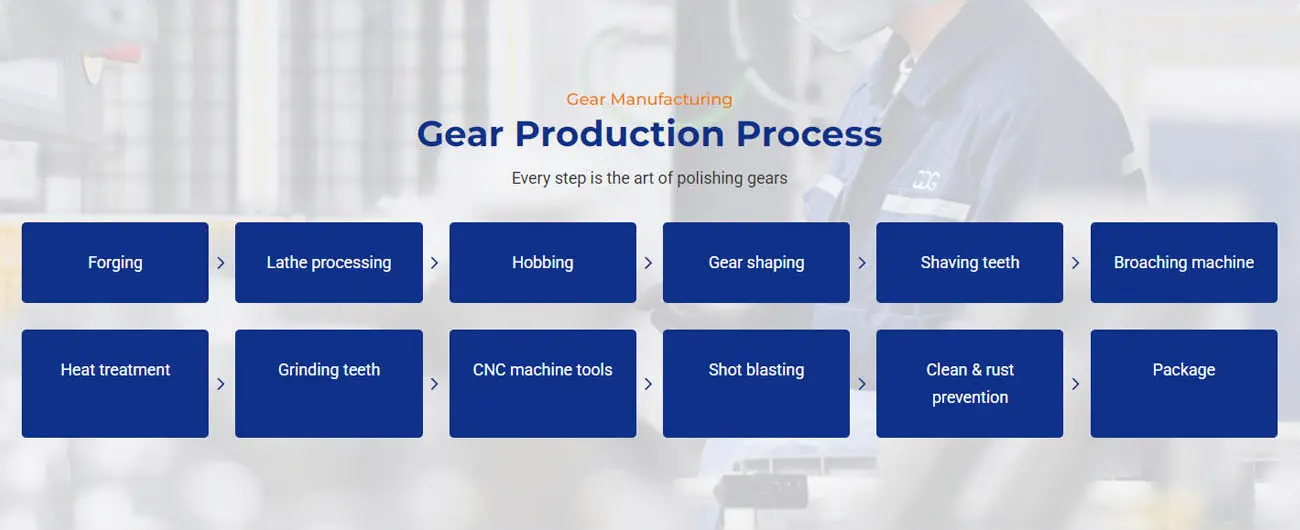
Every custom bevel gear is produced under a controlled gear manufacturing route designed for precision and durability. A typical process flow is:
-
Forging or bar cutting of shaft blanks
-
Lathe machining of shaft diameters and reference surfaces
-
Hobbing or shaping of gear teeth
-
Drilling, milling, and other CNC machining operations
-
Heat treatment (such as carburizing, quenching, tempering, nitriding)
-
Shot blasting and stress relief as required
-
Finish machining and grinding of journals and critical surfaces
-
Gear grinding (profile or worm grinding) where accuracy demands it
-
Cleaning and rust prevention treatment
-
Final inspection and packaging for shipment
Precision Gear Customization Process
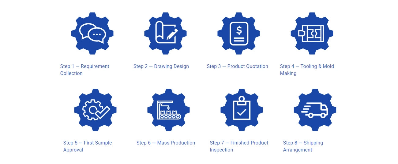
DD Gear follows a clear, eight-step customization process:
Step 1 – Requirement Collection
Customers provide design requirements, 2D drawings, 3D models, or physical samples, together with basic duty cycle information (torque, speed, life, installation).
Step 2 – Drawing Design & Optimization
Based on the provided drawings or samples, DD Gear prepares or optimizes detailed manufacturing drawings and shares them with the customer for confirmation.
Step 3 – Quotation
After the drawings and technical points are confirmed, we issue a precise quotation covering tooling, piece price, lead time, and quality requirements.
Step 4 – Tooling & Fixture Preparation
Once the price is confirmed, we arrange tooling and fixture production. Any tooling cost is agreed with the customer in advance and can be offset or refunded after mass orders, according to the commercial agreement.
Step 5 – First Sample Approval
After tooling and fixtures are ready, we manufacture the first sample batch—typically within about 30 days—and ship it to the customer for testing.The customer inspects and validates the samples in their gearbox or test bench and provides feedback on dimensions, performance, and any required adjustments.
Step 6 – Mass Production
When the sample is approved, we start mass production according to the agreed production plan and quality standards.
Step 7 – Finished Product Inspection
After production, we inspect hardness, dimensions, runout, tooth accuracy, and other critical characteristics to ensure full compliance with the drawing and standards.
Step 8 – Shipping Arrangement
Once inspection is passed and shipment is approved by the customer, we arrange booking, packaging, and delivery to the specified destination.
Quality Assurance & Inspection
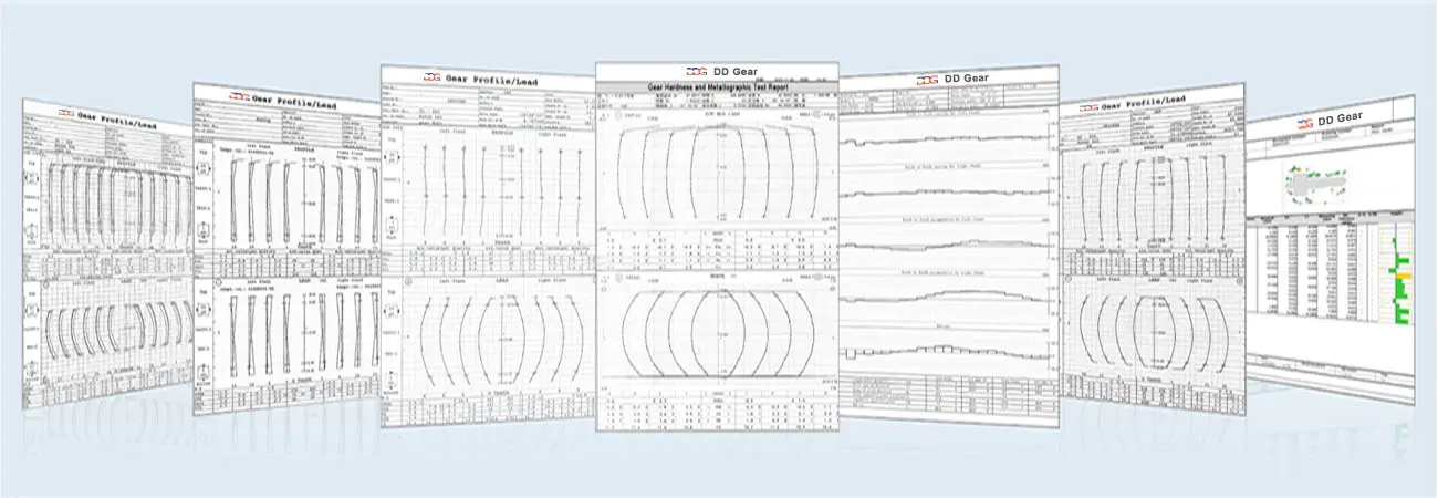
DD Gear applies the same quality philosophy to all precision gears:
-
Quality management systems based on ISO 9001 and IATF 16949
-
Process control from incoming material to final inspection, including:
-
Material certification and chemical composition checks
-
Hardness and case depth verification after heat treatment
-
Gear measurement for profile, lead, pitch, and runout
-
Surface roughness testing on gear flanks and journals
-
Dimensional inspection with calibrated gauges and CMMs
-
-
Traceability for each batch with inspection records and reports
- Optional documentation such as PPAP/FAIR packs on request
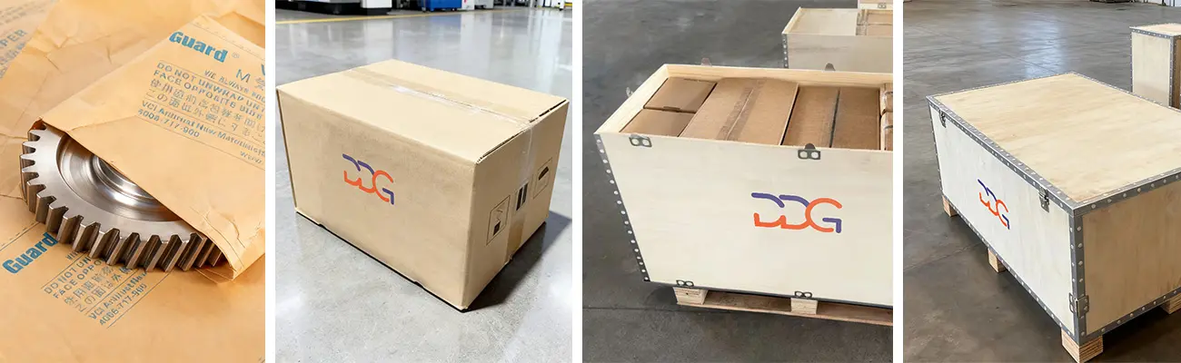
Packaging
Usage & Installation Notes
-
Bevel and hypoid gears must be installed with the specified mounting distances and alignment to achieve the designed contact pattern and noise level; small changes in position can significantly shift the contact.
-
During assembly, adjust shim packs or bearing preloads according to the specified procedures and verify the tooth contact pattern under light rolling load.
-
Use the recommended gear oil type and viscosity; hypoid gears often require EP gear oils that can handle sliding contact and high pressure.
-
Avoid mixing used and new gears from different sets; bevel and hypoid gears are usually matched pairs, and mixing may cause poor contact and premature failure.
-
Monitor operating temperature, vibration and noise in service; changes may indicate mounting shifts, bearing wear or tooth damage and should trigger inspection before serious damage occurs.
Company Strength – DD Gear
-
Specialized in small module, high-precision gears and shafts for EVs, humanoid robots, AGVs, and intelligent automation.
-
Integrated manufacturing from forging and machining to heat treatment and gear grinding.
-
Quality systems aligned with automotive standards, with experience supporting OEM and Tier 1 projects.
-
Engineering support covering concept feasibility, DFM reviews, and failure analysis feedback.
-
Global export capability with experience serving customers in multiple countries.
Q1: What information do you need for a bevel or hypoid gear quotation?
We usually need 2D drawings (PDF) and, ideally, 3D models; shaft angle and offsets; module and tooth numbers; gear type (straight / spiral / hypoid); material & heat treatment; torque, speed and duty cycle; required accuracy grade; and annual volume.
Q2: How do I choose between straight bevel and spiral bevel gears?
Straight bevel gears are simpler and typically used at moderate speeds where cost and simplicity are priorities. Spiral bevel gears provide more gradual tooth engagement, higher contact ratio and better load-carrying capability, and they are generally preferred for higher speeds and smoother operation.
Q3: When is a hypoid gear more suitable than a standard bevel gear?
Hypoid gears allow shaft offset, which is widely exploited in rear axles and differentials to lower the driveshaft and improve packaging, while also providing high torque capacity and smooth operation.
Q4: What accuracy grades can you achieve?
We manufacture bevel and hypoid gears according to the ISO bevel gear accuracy system and DIN 3965-based tolerances, as referenced in AGMA/ISO documents. The specific grade is agreed with you based on noise, load and cost targets.
Q5: Do you supply complete differentials or gearboxes?
DD Gear focuses on gear components—bevel/hypoid gears and related shafts. Complete differentials, axles and gearboxes are typically assembled by our customers or their system partners
Reliable precision gears for robotics, automotive, and beyond.
Custom Gears for Sliding, Swing & Industrial Doors | DD Gear
Automatic Door Gear from DD Gear is a range of custom-designed, small- to medium-module gears and shafts used in automatic sliding doors, swing doors, revolving doors and industrial doors (sectional, rolling, high-speed doors). In these systems, compact electric motors drive gearboxes and gear trains that must deliver high starting torque, smooth motion and very low noise while opening and closing heavy door leaves hundreds or thousands of times per day. Typical automatic door operators use one or more stages of spur and helical gears in combination with worm gears or bevel gears. Spur gears provide simple, efficient torque transfer for intermediate stages. Helical gears, with their angled teeth and higher contact ratio, help achieve quieter and smoother running, which is critical in hotels, hospitals, offices and residential buildings. Worm gears are often used for high reduction ratios and self-locking behavior, improving safety when the door is at rest and reducing backdrive from wind loads or manual pushing. In some operators, bevel gears change shaft direction between the motor, transmission and drive shaft or belt/chain. DD Gear manufactures Automatic Door Gears strictly on a custom, build-to-print basis. Using customer drawings or validated samples, we supply spur and helical pinions and gears, worm gears and worm wheels, bevel gears, gear shafts and related components for door operators. Through appropriate alloy steels, surface treatments, controlled heat treatment and precision machining, DD Gear helps door-operator OEMs and system integrators build drives that provide quiet operation, long life and reliable performance in entrances exposed to dust, temperature changes and frequent cycling.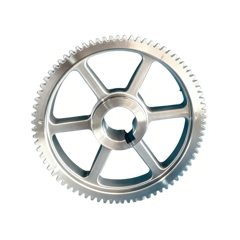
Custom Precision Gears for Electric Wheelchair | DD Gear
Electric Wheelchair Gear from DD Gear covers a family of small-module, custom-designed gears and shafts used in electric wheelchairs, powered mobility scooters and related assistive devices. In these products, compact electric motors drive wheel-side or centrally mounted gearboxes that must deliver high torque at very low vehicle speed, provide smooth, gentle acceleration and braking, and work reliably for years in both indoor and outdoor environments. Typical electric wheelchairs use a single-speed reduction between the high-speed motor and the drive wheel. This reduction is often realized by a worm gear stage, a spur/helical reduction stage, or a planetary gear set integrated into a wheel-side gearbox. Worm gears are commonly used because they can offer high reduction ratios and inherent self-locking behavior in many designs, helping the chair hold position on slopes when the motor is not powered. Spur and helical gears are used in intermediate stages or in designs where efficiency and low noise are prioritized. Planetary gear trains may be used when high torque density and compact packaging are critical, especially in wheel modules. DD Gear manufactures Electric Wheelchair Gears strictly on a custom, build-to-print basis. Based on customer drawings or validated samples, we supply worm gears and worm wheels, spur and helical gears, planetary gear components (sun, planet, ring), gear shafts and wheel-drive gear elements. Using case-hardening steels, controlled heat treatment and small-module precision machining or grinding, DD Gear helps mobility OEMs and system suppliers design drivetrains that offer quiet operation, safe holding behavior, good efficiency and long service life, enhancing comfort and confidence for end users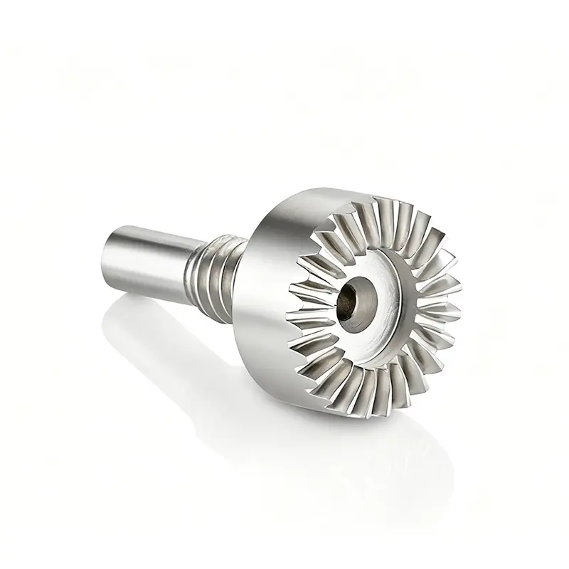
Custom Precision Gears for Surgical Robotics | DD Gear
Surgical Robot Gear from DD Gear covers a family of small-module, high-precision gears and shafts used in surgical robots, robotic-assisted surgical systems and related medical robotic platforms. In these applications, compact actuators drive robotic arms, wrists, end effectors and instrument modules that must deliver micron-level positioning, smooth motion and highly repeatable force control, often in minimally invasive procedures around critical anatomy. To achieve this, surgical robots commonly use spur and helical gears, planetary gear sets and gears integrated with harmonic or other precision reducers inside joint and instrument actuators. These gear stages must work with high-resolution encoders and advanced control algorithms, providing low backlash, high torsional stiffness and consistent friction characteristics across the full range of motion. At the same time, many components operate near the sterile field and must tolerate frequent cleaning and sterilization cycles, use biocompatible or low-outgassing materials and lubricants, and minimize particle generation. DD Gear manufactures Surgical Robot Gears strictly on a custom, build-to-print basis. Based on your drawings or validated samples, we supply spur, helical and bevel gears, planetary components (sun/planet/ring), gear shafts, small-module pinions and interface gears for precision reducers, using carefully selected alloy steels, stainless steels and, where specified, non-magnetic or corrosion-resistant materials. With controlled heat treatment, precision machining and (when required) ground tooth flanks, DD Gear supports surgical robot OEMs and system suppliers in building actuators that deliver precise, smooth and reliable motion, while supporting cleaning and sterilization concepts defined at the system level.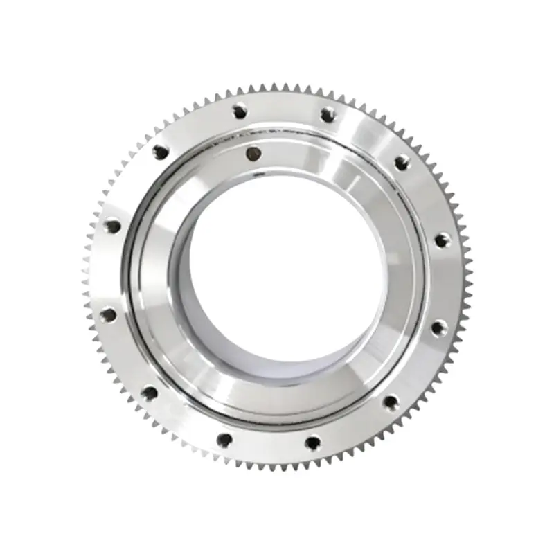
Custom Precision Gears for Automated Guided Vehicles | DD Gear
AGV Gear from DD Gear refers to a range of custom, small-module gears and shafts specifically engineered for Automated Guided Vehicles (AGV) and Autonomous Mobile Robots (AMR) used in warehouses, factories, distribution centers and logistics hubs. In these applications, compact electric motors drive wheel-mounted or centrally mounted gearboxes that must deliver high torque at low travel speed, provide smooth, precise motion control, and withstand continuous start/stop cycles in 24/7 intralogistics operations. Typical AGV drivetrains combine motor + reduction gearbox + drive wheel, often in a wheel hub or wheel-side gearbox design, while steering and lifting functions may use additional gear stages or screw drives. Single- or multi-stage spur and helical gears are common in wheel drives and intermediate stages, while planetary gear sets are widely used where high torque density and compact packaging are required, such as in drive wheels for heavy loads or AGV forklifts. In some architectures, gears are also combined with chain or belt stages to reach the final wheel or mast. Compared with traditional industrial vehicles, AGV/AMR systems place greater emphasis on low noise, smooth operation, positioning accuracy and long maintenance intervals. DD Gear manufactures AGV gears strictly on a custom, build-to-print basis, supplying spur and helical gears, planetary gear components (sun/planet/ring), bevel gears, gear shafts and wheel-drive gear elements based on customer drawings or validated samples. Using case-hardening steels, controlled heat treatment and small-module precision machining or grinding, DD Gear supports AGV and AMR OEMs in building transmissions that provide high efficiency, compact size, low NVH and long service life in demanding indoor and outdoor logistics environments.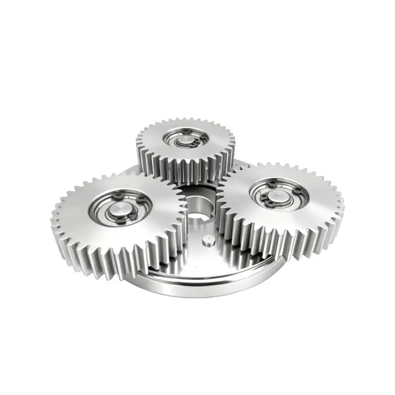
Custom Reduction Gears & Shafts for E-Motorcycle | DD Gear
E-Motorcycle Gear from DD Gear refers to a range of small-module reduction gears and shafts engineered for electric motorcycles, e-scooters, e-mopeds and high-power e-bikes. Instead of multi-speed gearboxes like those used in traditional ICE motorcycles, most electric two-wheelers use a single-speed reduction between the high-speed electric motor and the wheel. This reduction can be realized by hub-motor planetary gear sets, mid-drive spur/helical gear stages, or a combination of gear reduction + chain or belt drive. In hub-motor architectures, a compact planetary gear train is often integrated inside the wheel hub to reduce motor speed and increase wheel torque while keeping unsprung mass and noise under control. In mid-drive or centrally mounted motor layouts, the motor drives an intermediate shaft via spur or helical gears, and torque is then transferred to the rear wheel by a chain or belt. In both cases, the gears must handle high input speeds, frequent acceleration/deceleration, high torque at low road speed, outdoor exposure and strict NVH requirements, all within tight packaging envelopes. DD Gear manufactures E-Motorcycle Gears strictly on a custom, build-to-print basis. Using customer drawings or validated samples, we supply spur and helical pinions and gears, planetary gears (sun/planet/ring), gear shafts and hub-motor gear components. With appropriate case-hardening steels, controlled heat treatment and small-module precision machining or grinding, DD Gear helps electric two-wheeler OEMs and system suppliers build drivetrains that deliver high efficiency, quiet operation, compact packaging and long service life, supporting both urban commuting and higher-performance applications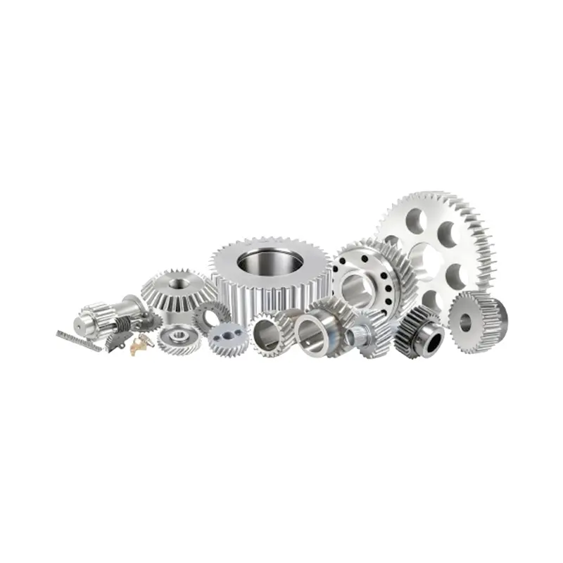
Custom Precision Gears for Packaging Machinery | DD Gear
Packaging Machinery Gear from DD Gear is a family of small- to medium-module, custom-designed gears used in form-fill-seal (FFS) machines, cartoners, case packers, palletizers, labelers and conveyor systems. In modern packaging lines, gears are responsible for coordinating motion between film feed, sealing jaws, product infeed, carton erection, filling, closing and outfeed. They must operate at high speed, often in 24/7 duty, while maintaining precise timing and position to avoid film waste, misaligned seals, product jams and unplanned downtime. Most packaging mechanisms rely on spur and helical gears in gearboxes and timing stages for parallel shafts. Spur gears provide simple, highly efficient torque transmission and are widely used in indexing, feed and cam drives. Helical gears, with their angled teeth and higher contact ratio, offer smoother, quieter running and higher load capacity, which is important in high-speed packaging halls where noise and vibration affect both productivity and operator comfort. In right-angle or compact layouts, bevel gears, worm gears or planetary sets may be used to change direction or achieve higher reduction ratios in a limited envelope. DD Gear manufactures Packaging Machinery Gears strictly on a custom, build-to-print basis. Based on your drawings or validated samples, we supply precision spur, helical, bevel gears, gear shafts and internal gears, using case-hardening steels, nitriding steels, stainless or corrosion-resistant grades, and selected engineering plastics where appropriate. Through controlled heat treatment, finishing and systematic quality control, we help packaging OEMs and retrofitters build gear trains that deliver stable speed ratios, smooth motion, low noise and long service life, even in demanding environments involving dust, humidity or washdownExploring The Science of Precision Gears

Custom vs Standard Gears: Balance Cost and Performance
Engineers and procurement teams often face the same choice when they design motion control systems. Should they pick ready-made standard parts or order a custom solution? In robotics, electric vehicles, and automation, standard power transmission components may not fit tight space limits or exact performance needs. At DD Gear, we focus on small-module, high-precision custom gears. These help balance initial costs with long-term reliability. This article covers the financial and performance differences to help you decide on your project. Understanding the Core Differences Picking the right motion gear set means knowing how standard parts and customized gear solutions compare in terms of design options and availability. Standard Gears Standard components are produced in large quantities based on catalog specifications to fit many general industrial needs. Fixed Dimensions: They follow catalog sizes exactly, so engineers often have to adjust the rest of the assembly around the gear. Predictable Availability: Stock items ship quickly, which helps during early prototyping when speed matters. Broad Tolerances: Built for general use, they usually come with average backlash and standard power handling. Customized Gears Customized gears are designed or adjusted to fit specific conditions, space limits, and operating stresses. Tailored Parameters: You control gear module sizes, tooth counts, pressure angles, and mounting details exactly as needed. Optimized Performance: Each small change targets real challenges, such as lowering gear whine or extending service life. Integrated Design: Shafts, splines, and gear profiles can be made as one piece, which reduces the total number of parts in tight spaces. The Cost Equation: Initial Outlay vs Total Cost of Ownership Looking only at the purchase price misses the full picture of integration and maintenance expenses over time. Upfront Procurement Costs Prices differ a lot between the two approaches because of production volumes and setup work. Standard Component Savings: Mass production keeps per-unit costs low, making standard spur gears or off-the-shelf bevel gears a practical choice for machinery with looser tolerances. Customized Gear Investments: Creating a customized input shaft or custom strain-wave gear requires initial tooling, design reviews, and setup time. Long-Term Value and ROI The real economic impact appears after thousands of operating hours in actual use. Hidden Costs of Standard Parts: Fitting standard precision industrial gears into tight spaces often needs extra adapters or larger motors, raising the total bill of materials. Extended Durability of Customized Gear Solutions: Using suitable alloy steels and targeted surface treatments on customized small-module gears lowers the chance of field failures and reduces downtime expenses. Performance Benchmarks in Emerging Applications New high-tech areas need reliable power transmission gear sets that fit in small spaces and handle changing loads. Precision and Noise Management Devices that need accurate positioning require controlled transmission errors and smooth meshing for quiet, steady operation. The Limitations of Catalog Standards: Standard off-the-shelf gear sets can add up to pitch errors, causing noticeable vibration and noise under load. Customized Profile Engineering: Specialized gear grinding and fine shaving let customized gear components achieve lower backlash and better noise-vibration-harshness performance. For comprehensive guidelines on managing transmission acoustics, engineers can consult the industrial benchmarks established by the National Electrical Manufacturers Association (NEMA) to align their system vibration goals. Power Density and Space Efficiency Robotic joints and vehicle drivetrains need maximum torque from very limited space. Standard Space Inefficiencies: Catalog options often use bulkier profiles for high loads, adding weight to robotic joints. Customized Material Optimization: Tailored heat treatments like gas carburizing or nitriding allow customized small-module gears to handle high torque without increasing size. To explore the deep material chemistry and heat treatment protocols that support high power density, designers can refer to technical resources provided by ASM International regarding surface hardening performance. When to Choose Standard vs Customized Gears The best decision depends on your production volume, precision needs, and physical limits of the application. Ideal Scenarios for Standard Gears Standard parts work well when design space is flexible and demands are moderate. Early Concept Prototyping: Testing basic ideas where exact torque and noise limits are still being defined. Standard Machinery Applications: Regular conveyor systems, simple packaging lines, or industrial equipment with fewer size restrictions. Tight Launch Schedules: Projects that need quick replacement parts when custom lead times are not possible. Critical Indicators for Customized Gears Custom solutions become necessary when standard parts limit system life or performance. Robotic Actuators and Joints: Humanoid and collaborative robot arms need customized robot reducer gears. These provide accurate positioning in compact housings. Electric Vehicle Drivetrains: Modern EV e-axle systems require customized high-speed input shafts. The shafts manage direction changes and meet strict NVH limits. Automated Guided Vehicles (AGVs): Warehouse robots need customized planetary gear sets. These deliver steady movement and smooth braking under varying loads. Specialized Medical Equipment: Surgical robotics and diagnostic scanners often use non-magnetic customized gears made from aluminum bronze or stainless steel. This choice supports safe operation near imaging equipment. High-End Power Tools: Professional drills and hammers need customized hardened spur gears. The gears survive sudden shocks inside small enclosures. The DD Gear Engineering and Customization Journey Turning a design into a finished part needs a partner that brings technical skill together with flexible manufacturing. Collaborative Development Protocol We follow a straightforward process that gives reliable results. Design and Optimization Phase: Our team checks the drawings you send and adjusts micro-geometries. This helps the teeth mesh smoothly and transfer power efficiently. Flexible Tooling and Sampling: We handle fast prototyping and deliver inspected first-article samples within 30 days for your approval. Comprehensive Manufacturing Infrastructure Our plant uses up-to-date machines to hold precision across different production volumes. Advanced Gear Machining: We run high-precision CNC gear hobbing, shaping, and grinding machines to hold accurate profiles. Strict Inspection Standards: Every customized shaft gear receives dimensional checks, surface hardness testing, and runout verification before shipment. Ready to Optimize Your Motion System? You do not need to limit your design to standard catalog parts. Whether you build a compact robotic joint, a high-torque AGV drive unit, or a quiet electric vehicle drivetrain, our engineering team stands ready to assist. Contact DD Gear today at support@ddgear.com or via WhatsApp at +8615356970628 to review your drawings and receive a technical quotation for your customized gear needs. FAQ Q: What is the typical lead time difference between standard and customized precision industrial gears? A: Standard catalog parts are often ready right away or arrive in a few business days. Customized small-module gears go through design review, tooling, and machining. Sampling takes 2 to 4 weeks before batch production begins. Q: How does gear backlash differ between off-the-shelf options and customized gear sets? A: Standard catalog parts use wider tolerances to fit many assemblies. This can lead to varying backlash. Customized gear sets control center distances and profile modifications more tightly. They deliver stable, repeatable performance in precise applications. Q: Can custom materials be specified for gears operating in harsh or specialized environments? A: Yes, this is one of the main advantages of custom parts. Standard catalog gears are limited to common carbon steels or basic plastics. Customized manufacturing lets you choose special alloys, stainless steels, or non-magnetic materials like aluminum bronze. These provide corrosion resistance or work for medical use. Q: Can customized gears improve the overall efficiency of compact planetary gear systems? A: Yes. Adjustments to tooth micro-geometry, pitch, and surface treatments cut friction and mesh resistance. This reduces energy losses and heat buildup in tight assemblies compared to standard catalog parts.

Best Robotic Arm Gears: Balance Precision Torque & Stability
Modern industrial automation and advanced robotics need motion systems that perform repetitive tasks with consistent accuracy. At the center of these systems sit robotic arm gears. These parts control how smoothly, precisely, and dependably each joint operates. Design engineers and procurement managers face a careful choice. They must weigh physical limits, workload demands, and operating conditions when selecting robotic joint gears. As a manufacturer focused on small-module high-precision gears, DD Gear develops drive solutions built for new automation areas. We know standard off-the-shelf gears rarely match exact needs. That is why we emphasize flexible, accurate manufacturing. This article examines the main factors that help achieve the right balance in high-performance robotic arm gears. Key Performance Requirements for Robotic Arm Gears Picking the right drive gears requires a clear view of how forces interact during fast acceleration and slowing down. Understanding Rotational Precision Precision shows how closely a robotic end-effector can return to the same position after many cycles. Low-Backlash Design: Reducing play between gears matters greatly for tasks that need high repeatability. Tooth Profile Modification: Changing gear tooth shapes helps handle small bends under dynamic loads. Transmission Error Control: Steady rotation keeps speed even and prevents small hesitations during assembly work. Maximizing Torque Density Robotic structures must stay light for quick movement while carrying heavy loads. Material Selection: High-grade alloy steels let gears handle sudden shocks without breaking. Advanced Heat Treatment: Methods like gear carburizing or nitriding create hard surfaces with a strong inner core. Optimized Face Width: Adjusting contact areas spreads stress evenly across teeth and reduces early wear. Ensuring Long-Term Stability A robotic system represents a long investment. It must run for extended periods in busy factories with limited maintenance stops. Low Noise and Vibration: Cutting mechanical shake protects sensors and encoders from early damage. Friction and Thermal Control: Good gear surface finishes limit heat buildup, which helps avoid expansion problems and keeps parts aligned. Wear-Resistant Meshing: Durable gear coatings maintain steady contact patterns through millions of cycles. Choosing the Right Gear Profiles for Robotics Different joints in a multi-axis robot need specific gear designs to manage forces in various directions. Helical Robotic Arm Gears Helical gear teeth come together gradually instead of all at once. This creates smoother power transfer. Gradual Tooth Engagement: The step-by-step contact lowers noise in collaborative robot areas where people work nearby. Higher Load Capacity: Angled teeth increase contact area and spread heavy forces more safely. Axial Force Consideration: Designers must plan for thrust loads from the angled teeth by choosing suitable bearings. Spur Robotic Arm Gears Spur gears move power between parallel shafts. They offer good mechanical efficiency without producing axial forces. Direct Power Transmission: Straight teeth transfer energy with little internal friction. Simplified Assembly Integration: No thrust loads mean lighter housings and more compact bearing setups. Noise at High Speeds: Teeth meet along their full face at the same time, so these gears suit lower-speed or secondary joints best. Planetary Robotic Arm Gears Planetary gear setups spread load across several points. They work well where space stays tight. Compact Coaxial Layout: Input and output shafts line up directly, saving room in crowded joint areas. Excellent Load Distribution: Power moves through multiple planet gears, which lowers stress on any single part. High Torsional Stiffness: The structure holds alignment firmly and prevents position shifts under sudden heavy loads. Addressing Challenges with Customized Solutions Standard gears frequently miss the mark when robots operate in special conditions or need exact performance. Materials for Harsh Environments Robots in pharmaceutical production, food processing, or semiconductor cleanrooms meet particular demands. For insights into standard material benchmarks in challenging engineering environments, you can consult technical resources on MatWeb Material Property Data. Corrosion Resistance: Stainless steel or bronze options resist oxidation during chemical washdowns. Non-Magnetic Operations: Certain alloy mixes allow safe use near medical imaging or surgical tools. Specialized Surface Coatings: Low-friction layers cut the need for external lubricants and lower contamination risks in clean areas. Overcoming NVH Challenges Noise, vibration, and harshness problems can disturb precision sensors and cause early breakdowns. Phase Matching Adjustments: Special relationships between mating gears break up repeating frequencies. Surface Roughness Optimization: Precision grinding after heat treatment removes tiny imperfections that create gear whine. Customized Lubrication Interfaces: Built-in oil channels keep cooling steady at key friction points. The Importance of Customized Manufacturing Each robotic application brings its own limits. A standard approach rarely works for advanced automation. Flexible Manufacturing Processes Reliable production must support custom changes without large minimum order quantities. Tailored Engineering Layouts: Adjustments to tooth count, module size, and bore dimensions help parts fit existing spaces exactly. Rapid Prototyping Windows: Custom samples arrive in two to three weeks so teams can test them in real conditions early. Advanced Metrology Verification: Full gear testing confirms custom parts stay within required tolerances before shipment. Comprehensive Design Support Close cooperation between the gear maker and robot designer leads to better long-term results. For foundational design principles regarding gear geometry and stress calculations, engineers frequently refer to the KHK Gear Technical Reference. Application Requirement Review: Checking load profiles, speeds, and duty cycles guides material choices. Optimization of Layouts: Changes to tooth geometry reduce stress points and extend service life. Documented Quality Controls: Detailed reports on hardness and runout data support smooth production integration. Ready to Optimize Your Robotic Drive Performance? Finding the right mix of precision, torque, and stability calls for gears made for your specific needs. At DD Gear, we focus on high-precision, small-module custom configurations that match your engineering requirements. Whether you need quick prototypes for a new robotic arm or a steady production partner for automated guided vehicles, our team stands ready. Contact DD Gear today to share your 2D drawings or project details with our engineering specialists. Let us develop your next transmission solution together. FAQ Q: Why are helical profiles preferred over spur profiles in collaborative robot joints? A: Helical profiles mesh in a gradual way instead of all at once. This steady contact cuts down vibration and high-frequency noise. The result fits collaborative robots that work near people and need quiet, smooth motion. Q: How does heat treatment impact the torque capacity of small-module robotic components? A: Carburizing forms a hard outer layer on the teeth while the core stays tough and flexible. Small parts can then carry high torque and handle sudden loads without breaking. Q: What materials are recommended for precision components operating near sensitive medical equipment? A: Work near MRI scanners calls for non-magnetic materials. Aluminum bronze, brass, and austenitic stainless steels work well. These pair with low-outgassing lubricants made for such settings. Q: How do environmental factors like extreme temperatures affect robotic arm gear selection? A: Big temperature swings change backlash and tooth alignment through expansion or contraction. Engineers pick alloys with low expansion rates. They also use lubricants that hold steady viscosity across the full temperature range.

Top Questions to a Precision Gear Supplier Before Ordering
Finding the right precision gear supplier goes beyond simply comparing price quotes. For engineering and procurement teams working in fields like robotics, electric vehicles, and smart automation, the transmission partner you pick affects product lifespan, how quietly it runs, and overall system reliability. As a specialist in industrial transmission parts, DD Gear provides customized, small-module high-precision gears and components built for these growing applications. Asking the right technical and operational questions early helps you tell apart true manufacturing partners from basic component sellers. Technical Capabilities and Accuracy Verification Before you sign a manufacturing agreement, check that the supplier has the right equipment and testing methods for small-module parts. Working with a specialized precision gear supplier ensures your tight tolerances hold up during actual production. Can Your Production Line Meet Small-Module High-Precision Standards? Handling small-module profiles needs dedicated gear-cutting machines, fine micro-grinding tools, and accurate control over cross-axis geometry. Take time to review the supplier’s usual processing range and their quality checking equipment to confirm they can deliver steady results over time. Module Scope and Precision: Choose a supplier experienced with small-module gear production from module 0.2 to module 1.5 that maintains quality suitable for demanding applications. Measurement Infrastructure: The workshop should have advanced inspection tools like specialized CNC gear measuring centers to check profile deviation, helix errors, and total composite error values. Geometric Uniformity: Accurate machining makes sure each tooth carries the load evenly, which cuts down on early wear in heavy-use industrial settings. How Do You Achieve Noise-Reducing Operations for Sensitive Applications? Quiet transmission performance matters a lot in high-end uses such as medical devices and robotic joints. Getting low noise levels depends on refined tooth shapes and specific surface treatments instead of ordinary machining. Tooth Profile Modification: Adjusting the tooth tip and profile crown helps balance out flex under load and creates smoother meshing. Advanced Gear Surface Grinding: Switching from basic shaving to precision gear grinding lowers surface roughness and reduces high-frequency noise. Phase Matching Integration: In multi-stage setups, careful phase matching during assembly spreads out small variations to avoid vibration and sound buildup. Tailored Solutions and Specialized Material Expertise Today’s high-performance applications seldom work best with off-the-shelf items. A supplier focused on customized gear development makes sure every detail fits your torque and space needs exactly. What Is Your Process for Delivering Customized Gear Solutions? Creating custom gear components calls for step-by-step teamwork between engineers to avoid mistakes and shorten development time. A good partner walks you through a clear review process before full production starts. Design Optimization Review: It starts with a close look at your 2D drawings or sample parts to check how easy they are to make and spot possible stress points. Rapid Sample Turnaround: A responsive, customized gear manufacturer usually delivers prototype samples in 2 to 3 weeks for your initial testing. Flexible MOQ Volumes: Early-stage projects in new industries often need lower minimum order quantities (MOQ), then move to regular delivery schedules once production scales up. How Do You Select Materials for Harsh Operating Environments? Different growing industries need transmission parts with very different mechanical qualities. A capable supplier should offer various alloys, engineering plastics, and specific heat treatments. Robotics and Robotic Joints: These parts often use high-strength alloy steels with carburizing or nitriding to build a hard outer layer while keeping a tough core that handles shocks. Medical Equipment and Surgical Robotics: For MRI-safe or chemical-resistant needs, parts come from special stainless steels or high-grade engineering polymers. Electric Vehicle (EV) Transmissions: High-speed EV drivetrains require premium alloy steels that manage fast shaft speeds and big temperature swings. Industry Applications and Structural Problem Solving The real test of a precision gear supplier shows up in their field experience. Seeing how custom components fix actual mechanical issues helps you judge their real expertise. How Do Your Gear Solutions Solve Common Failures in Emerging Industries? A strong supplier does more than make parts to spec. They work as a transmission solution provider that helps stop breakdowns in the field. Quality custom setups address mechanical problems in several new industries. Automated Guided Vehicles (AGV): Heavy-duty AGV drive wheel gearsets deal with strong impacts and repeated start-stop cycles. Customized planetary gear systems with hardened surfaces help prevent pitting and broken teeth. Professional Electrical Tools: High-torque tools like angle grinders and rotary hammers need compact, tough gear sets. Hardened customized spiral bevel gear pairs allow smooth right-angle power transfer in tight spaces. Automated Door Systems: Commercial doors must operate smoothly and quietly through millions of cycles. Customized helical gear sets reduce noise and extend the time between maintenance. Can You Provide Real Examples of Successful Transmission Solutions? Looking at actual project outcomes shows how well a supplier balances performance numbers with cost realities. These examples highlight how custom work improves system efficiency. Marine Propulsion Upgrades: Marine outboard gearsets stay underwater and face salt corrosion plus gear noise. Switching to hardened customized spiral bevel gear sets from marine-grade alloys boosts corrosion resistance and quiets operation. Robotic Joint Optimization: Humanoid robot actuators need compact designs with high torque. Customized strain-wave gear sets and customized harmonic reducer components increase accuracy while cutting overall joint weight. EV E-Axle Refinement: Electric vehicles require very quiet interiors, so transmission NVH performance is key. Customized input shaft configurations with adjusted helix angles improve gear mesh smoothness. To learn more about standard industrial gearing principles and performance calculations, engineers can consult the comprehensive resource guides maintained by the British Gear Association (BGA) or explore the manufacturing standards library at the American National Standards Institute (ANSI). Ready to Optimize Your Transmission Strategy? Avoid letting standard catalog options limit how your product performs in real use. Team up with a specialized precision gear supplier that understands the tight accuracy and quiet running needs of modern engineering work. Contact DD Gear today to send your drawings, get a full technical review, or arrange a prototype run for your customized gear project. Email: support@ddgear.com Phone: +8618257981010 WhatsApp: +8615356970628 FAQ Q: What are the main causes of gear whine in high-speed transmissions? A: Gear whine often stems from quick vibrations. These come from small errors in tooth shape plus shifts in mesh stiffness when the gears carry load. Careful grinding, crown tweaks, and solid housing alignment all help lower the noise. Q: Why is small-module gear manufacturing considered more difficult than large-scale production? A: Small-module gears need tighter tolerances and thinner teeth. Even slight moves in tool position or during heat treatment can cause visible warping, so shops rely on advanced machines and careful checks. Q: How does customized gear geometry improve overall system efficiency? A: Custom shapes let engineers adjust tooth contact ratios. They can also choose smoother finishes and materials that cut friction. Lower heat follows, and the drive motors can stay smaller while still running well. Q: How does proper heat treatment affect the service life of an AGV drive gear setup? A: AGVs run through repeated starts and stops under heavy loads. Controlled carburizing or nitriding on an AGV drive gear setup forms a hard outer layer that resists pitting. The core stays resilient enough to handle sudden shocks.

Steel, Brass, or Plastic? Gear Material Selection Guide
Choosing the right gear components for modern industrial applications means balancing torque, running speed, weight, and the conditions where they will work. At DD Gear, we specialize in small-module high-precision metal gears and customized powertrain solutions for growing areas such as robotics, electric vehicles (EVs), automated guided vehicles (AGVs), medical devices, electrical power tools, and automated machinery. When you build a compact motion control system, the gear material selection process forms the real foundation of performance. Different materials bring their own mechanical strengths depending on the job. This guide compares steel, brass, and plastics from an engineering perspective so you can decide which one fits your specialized transmission systems best. Selecting the Right Metallic Materials for Heavy-Duty Performance Metallic alloys still serve as the main option when you need strong structure, good fatigue resistance, and lasting durability under steady stress. For heavy loads and fast transmission speeds, the right metallurgy makes the difference. Carbon Steel and Alloy Steel Solutions Steel stands as the standard for high-torque applications where structural strength must hold firm. Picking the proper grade helps avoid early mechanical problems when loads change. High Torque Density: Carbon and alloy steels deliver strong tensile strength, which makes them suitable for heavy-duty input shaft gear setupsin electric vehicle transmissions. Advanced Heat Treatment Compatibility: Steel works well with carbonitriding and case hardening. These processes improve wear resistance for motor wheel assemblies in automatic guided vehicles. Precision Machining Tolerances: Steel allows fine gear grinding, so we can reach tight dimensional alignment for low-noise planetary gear trains. Brass and Bronze Component Options Copper-based alloys have long played a role in low-speed, high-friction setups where surface contact matters. Their natural qualities solve tricky friction issues in limited spaces. Low Frictional Coefficients: Phosphor bronze and brass often appear in custom small-module worm gear pairs. They cut friction and heat when sliding against steel parts. Excellent Anti-Galling Properties: These materials limit surface welding under ongoing load, which keeps mesh cycles smooth in automatic door drive mechanisms. Corrosion Resistance: Brass stands up to moisture and chemicals, so it suits surgical equipment and automated lab diagnostics instruments. Evaluating Engineering Plastics for Lightweight and Quiet Operations Modern high-performance polymers have moved past basic uses. They now offer solid alternatives to metals in applications where weight and sound levels matter. Thermoplastics and Reinforced Polymers Engineering plastics bring features that metals cannot copy, especially when reducing mass and damping noise. They fit well in delicate, fast-moving control assemblies. Acoustic Noise Reduction: Polymers absorb vibrations naturally, which makes them good for medical imaging devices that need quiet surroundings for patients. Self-Lubricating Operations: Materials like POM (Polyoxymethylene) or nylon run efficiently with little extra lubrication. This helps maintenance in cleanroom automation systems. Substantial Weight Savings: Switching from steel to reinforced plastics lowers rotational inertia. This improves thermal management and battery life in handheld electrical power tools. Comparing Material Properties for Specific Emerging Industry Applications Material choice depends on matching its mechanical traits to the actual demands of the working environment. Each sector brings its own issues with temperature changes, chemical contact, and torque loads. Robotics and Joint Actuator Demands Robotic applications need a careful mix of structural strength, high torque output, and low weight to reach good efficiency. The material must handle stresses from multiple directions during movement. Hybrid Material Integration: Pairing customized lightweight alloy steel pinions with specialized polymer outer rings improves the weight-to-torque balance in humanoid robotic joints. Deflection Resistance: High-modulus steel stops tooth bending during sudden start-stop cycles in collaborative robotic arms. This keeps positioning accurate. Medical Device and Cleanroom Requirements Medical equipment calls for clean materials, regulatory compliance, and steady reliability throughout its working life. Material choice affects both patient safety and how long the equipment lasts. Non-Magnetic Compliance: For devices used near strong magnetic fields like MRI scanners, we turn to customized non-magnetic brass or high-performance PEEK polymers. Sanitization Longevity: Certain engineering plastics endure repeated chemical sterilization without cracking or breaking down over time. The Role of Customized Engineering Services in Material Selection No single material solves every engineering limit, which is why standard catalog parts often miss the mark in specialized work. Tailored development makes sure your system runs exactly as planned. Why Off-the-Shelf Options Fall Short Mass-produced gears seldom match the exact torque needs, space limits, and service life required by new automated machinery. Standard parts bring performance compromises. Incompatible Tolerances: Commercial gears frequently lack the precise tooth profile changes needed to remove extra gear whine in high-speed electric motorcycle drivetrains. Suboptimal Material Grades: Off-the-shelf components rarely use the exact alloy or polymer mix that would boost efficiency in compact planetary gear sets. How DD Gear Delivers Tailored Transmission Solutions At DD Gear, our engineering team helps your project from the start with material selection. We stay with it through testing and into full production. Our manufacturing steps fit the needs of your specific application. Comprehensive Customization Process: Our full service begins with a review of your blueprints. It moves to clear pricing and ends with the creation of custom tooling. Rigorous Quality Verification: Every customized batch receives thorough checks. These include surface hardness tests, dimension measurements, and runout inspections. Application-Specific Optimization: We match gears to your conditions. This could mean a customized stainless steel helical gear for a medical fluid pump. Or it could be a hardened alloy spur gear for a heavy-duty industrial conveyor. Next Steps for Engineering Teams Good drivetrain design needs a full look at gear material choices. Teams weigh strength limits, operating conditions, and total cost. Knowing how steel, brass, and plastic differ can stop early failures and raise system performance. Ready to Move Forward with Your Next Project? Work with a partner who knows small-module high-precision needs. You can find more material data sheets and manufacturing details in technical guidelines on platforms like the International Organization for Standardization (ISO) for basic material mechanics or the MatWeb Material Property Data archive for deeper polymer and alloy information. Contact DD Gear today to get a customized design consultation and technical quote for your next high-precision gear project. FAQ Q: Can plastic gears reliably replace steel gears in high-torque automation applications? A: Plastic gears often fall short of steel when torque reaches high levels. Their tensile strength stays lower. Reinforced polymers still suit medium-load work. In these cases, lower weight, built-in lubrication, and quieter running matter more than peak load capacity. Q: How does surface heat treatment affect the performance of steel gears in EV drivetrains? A: Treatments such as case hardening and nitriding form a tough outer layer on steel gears. The core remains more flexible. This change raises wear resistance along tooth profiles. It also helps the gears manage sudden loads without early damage. Q: What are the main warning signs that the wrong gear material was selected for an application? A: Teeth may wear faster than expected. Pitting can appear early along the pitch line. Operating noise rises. Extra heat builds up during runs. In some cases, teeth break under normal loads. Q: Why is brass preferred over steel for worm gear wheel applications? A: Worm gear drives create heavy sliding contact. Brass or bronze wheels on a steel worm shaft cut friction. Heat stays lower, and galling is avoided. The full assembly then lasts longer in service.

Planetary Gear vs Harmonic Drive: Which Wins for Precision
When building motion control systems for new industries, choosing the right speed reduction method stands out as one of the biggest decisions engineers and purchasing managers face. At DD Gear, we focus on small-module high-precision gears and practical drivetrain solutions. We help teams work through these mechanical options so they end up with reliable systems that perform well in real conditions. The choice between planetary and harmonic drive comes up regularly when designing compact equipment. Each system has its own structure, way of handling loads, and particular strengths. This guide explains the main technical differences clearly. It will help you pick the one that fits your application and daily operating needs. Understanding the Core Mechanical Principles It makes sense to first understand how each system moves torque and reduces speed before comparing how they actually perform on the job. The Mechanism of Planetary Gear sets Planetary gear systems use an arrangement that spreads the load, much like planets circling a sun. For a deeper look at the foundational math and kinematics behind these configurations, you can consult the KHK Gear Technical Reference on Planetary Gear Systems. Sun Gear: This central gear takes the rotational force coming from the electric motor. Planet Gears: Several spur or helical gears spin around the sun gear while they mesh with an outer ring. Planet Carrier: This assembly connects the centers of the planet gears and sends out the final torque. Ring Gear: The fixed internal gear inside the housing that keeps the planet gears on track. The Mechanism of Strain-Wave Harmonic Drives Harmonic drives work through a flexible bending action instead of stiff tooth contact. Wave Generator: An elliptical steel disk with a flexible bearing that serves as the fast input. Flexspline: A thin-walled steel cup with outer teeth that bends as it rotates. Circular Spline: A rigid ring gear fixed to the outer case with slightly more teeth than the flexspline. Key Performance Comparisons for Engineering Decisions Looking at the actual physical features of planetary versus harmonic drive helps engineers weigh torque needs against cost and available space. Torque Density and Spatial Limitations The best choice depends on how much force the gear must deliver inside tight limits. Harmonic Drive Strengths: These units perform well in small spaces. They reach high reduction ratios in a single stage, although they need attention to heat during long running times. Planetary GearSet Strengths: Multi-stage versions can grow longer in length, but they manage sudden shock loads well by sharing the stress across several gear teeth at the same time. Backlash Control and Rotational Accuracy Good positional accuracy and low lost motion matter a lot for precise industrial positioning equipment. Harmonic Drive Attributes: They reach very low backlash because of the continuous elastic tooth contact. This makes them strong for tasks that need exact positioning. Planetary GearSet Attributes: Standard designs have some natural clearance, but careful manufacturing and tooth shaping can reduce it enough for applications that need quick response. Planetary Gears and Harmonic Drives in Modern Motion Control Different working environments and daily usage patterns usually point toward one type over the other. Robotics and Joint Actuation Robotics needs power transmission parts that manage changing forces while staying light. Humanoid Robot Joints: Harmonic drive parts show up frequently in shoulder and elbow joints. Their lighter weight helps keep the overall moving structure from feeling too heavy. AGV Drive Wheels: Planetary gearsets often work better for automated guided vehicles. Their solid build stands up to constant floor vibrations and heavy loads coming from above. Medical Equipment and Automotive Systems Medical devices and car sub-assemblies need quiet running and a steady service life over time. Surgical Imaging Systems: Small-module harmonic drives give smooth rotation during fine adjustments without sudden jerks or stops. EV Steering Systems: Precision planetary gears suit electric vehicle power steering modules. They offer good durability and consistent wear patterns during daily use. The Value of Specialized Manufacturing and Customized Services Standard reducers from the shelf sometimes miss the mark when torque requirements fall outside normal ranges, space is unusual, or conditions are demanding. At DD Gear, we close this gap with focused engineering, careful production, and fast technical support. To explore how advanced processing shapes performance, you can review published research on precision gear tooth modifications and micro-geometry optimization via ScienceDirect.Our team shapes performance through detailed work on tooth profiles and micro-geometry. This approach helps your system run smoothly in these ways: Tailored Micro-Geometry: We adjust tooth shapes and helix angles to improve contact and lower noise levels. This becomes especially useful in medical equipment where quiet operation is important. Advanced Material Selectivity: Our engineers pick the right alloys and heat treatments based on your actual environment, including options suitable for vacuum conditions. Flexible Project Fulfillment: We offer prototyping within 2 to 3 weeks and adjustable order quantities. This supports projects from the first drawings all the way to full production runs. Conclusion The decision between planetary and harmonic drive comes down to what matters most in your project — structural stiffness, weight limits, positioning accuracy, and overall budget. When you need strong resistance to shocks, long running hours, and better cost control, a customized planetary gear set often serves as the most practical choice. When space is extremely tight and very low backlash is the top priority, a harmonic drive system frequently becomes the better route. Are you working to improve the drivetrain in your next automation platform, robot joint, or specialized industrial device? Contact DD Gear today. Get direct feedback on your design and a clear technical quotation for your custom precision gear components. FAQ Q: What causes mechanical efficiency loss in harmonic drive systems compared to planetary gear sets? A: The main cause comes from the constant bending of the flexible cup and the friction inside the wave generator bearings. Planetary systems usually have less internal friction because they use rolling contact between solid parts. This often results in better energy efficiency during steady operation. Q: Can planetary gear systems achieve the same low-backlash characteristics as harmonic drives? A: Standard planetary units show some backlash, but high-precision versions can reach very low levels. Precision grinding and careful assembly help close the difference, as shown in various technical studies over the years. Q: Which gear system offers better reliability under sudden mechanical shock loads? A: Planetary gear sets generally handle sudden shocks better. The forces spread across multiple planet gears at once. Harmonic drives can sometimes struggle with torque spikes that stress the flexible cup or cause tooth skipping if the load becomes too high. Q: How does DD Gear support customized project requirements for specialized automation industries? A: We provide full custom engineering support, including tooth profile adjustments to reduce noise and material choices for tough conditions. To help teams move faster, we offer prototyping in 2 to 3 weeks and flexible minimum order quantities that fit different project scales.

High-Precision Gear Solutions for Industrial Automation
Smart manufacturing keeps moving forward. The performance of any system often depends on small mechanical parts. Engineers and procurement teams know this when they work on surgical robot arms or electric vehicle drivetrains. Choosing the right transmission parts is not just about picking one component. It affects long-term reliability and performance. DD Gear focuses on customized small-module high-precision gears and transmission solutions. These parts serve robotics, EVs, AGVs, medical equipment, and power tools. We put accuracy and specialized engineering first. Global OEMs can therefore reach new levels in modern automation. The Critical Role of Small-Module Gears in Automation Small-module gears work as the main drive parts in modern intelligent systems. They need high accuracy to keep motion smooth and predictable. Optimized Performance for Robotics and Collaborative Arms Modern robotics needs parts that save space yet still deliver high torque density and strength. Customized Planetary Gear Sets: Engineers choose planetary setups because they spread the load across multiple contact points. This makes them suitable for high-torque transfer in tight robotic joints. Weight and Balance: Small-module high-precision gears allow smaller motors and lighter housings. A robot’s power-to-weight balance improves as a result, and movements become more natural. Backlash Control: Surgical and collaborative robots need low mechanical play between teeth. This keeps positional accuracy high during delicate tasks. Enhancing NVH in Electric Vehicle (EV) Drivetrains Electric vehicles are growing fast. The quiet motor no longer hides gear noise, so new solutions are required. Transmission Error Mitigation: Transmission errors occur when the output gear does not match the input rotation exactly. These errors often create sharp gear whine. High-Speed Input Shafts: EV motors often run above 15,000 RPM. Automation gear solutions must handle rapid vibrations and dynamic loads without failure. Specialized Geometry: Tooth profile micro-geometry can be adjusted. This shifts noise frequencies beyond human hearing and improves passenger comfort. High-Precision Technology and Customized Engineering Peak efficiency in automation gear solutions depends on advanced manufacturing and a clear understanding of gear micro-geometry. Advanced Tooth Micro-Geometry Modifications Standard gears often miss the strict NVH targets found in today’s electric and intelligent systems. Customized Lead Modification: Adjusting gear teeth along their length prevents edge loading. Forces are then distributed more evenly. Profile Crowning: A gentle curve on the tooth surface keeps the contact area centered. Shaft misalignment has less effect as a result. Tip Relief: Removing a small amount of material from the tooth tip allows smoother entry into the mesh zone. Engagement noise drops accordingly. High Overlap Ratios: More teeth stay in contact at any time. The load spreads more evenly, and sound levels fall further. Precision Grinding and Finishing for Reliable Motion Surface quality on a gear face directly affects friction, heat, and drag at high speeds. ISO Grade 4–5 Accuracy: For high-speed work, DD Gear holds flank accuracy up to ISO 1328 Grade 4–5 according to drawing requirements. Superfinishing Techniques: Precision polishing brings surface roughness down to a mirror finish. Metal-to-metal friction and heat drop sharply. Shot Peening: This step improves surface texture for better lubricant retention. Fatigue life also increases. Further details on these techniques and their effects on system dynamics appear in resources from SAE International. Diverse Automation Application Scenarios Different industrial settings create unique challenges. Standard gears often cannot meet these needs, so customized solutions become necessary. Automated Guided Vehicles (AGV) and Logistics Mobility Warehouse AGVs and AMRs move heavy loads around the clock. Their reduction gears must stay durable under constant use. High Torque at Low Speed: AGV drivetrains often pair a motor with a wheel-side planetary gearbox. This setup supplies the torque needed for heavy lifting and transport. 24/7 Service Life: We supply customized helical gears and planetary components that reduce power loss as heat. Battery runtime between charges improves. Environmental Resilience: Gears in logistics face dust, humidity, and frequent start-stop cycles. They must resist wear under these conditions. Precision Gear Solutions for Medical and Surgical Robotics Medical imaging systems and surgical robots need smooth motion without intrusion. Image quality and patient comfort both depend on this. Customized Quiet Motion: Small-module helical gears replace standard spur gears. The higher contact ratio cuts vibration during patient table movement. Non-Magnetic Material Selection: MRI-adjacent modules use customized gearsets in aluminum bronze, brass, or austenitic stainless steel. Magnetic interference stays low. Biocompatibility and Cleanliness: Parts near sterile fields withstand repeated cleaning and sterilization. Particle generation remains minimal. Technical specifications for these high-precision motion systems are often reviewed by the IEEE Robotics and Automation Society. The DD Gear Customized Service Framework Our partnership approach makes sure every transmission component fits its final assembly and operating life. Rapid Prototyping for Research and Development Speed matters for R&D teams that develop next-generation automation. 2–3 Week Lead Times: We offer rapid gear prototypingafter drawing confirmation and for suitable small-module prototype projects. Flexible MOQs: A single prototype for research or a small batch for pilot builds is available. Order volumes stay flexible to match project growth. Design for Manufacturing (DFM): Our engineers review 2D and 3D drawings. They suggest changes that lower noise and weight without raising production costs. Full-Process Quality Control and Traceability Consistent quality across large runs comes from a strict management system. Strict Inspection Protocols: Every batch is checked for hardness, runout, tooth profile, and pitch deviations on CNC gear measuring centers. Materials and Heat Treatment: We select high-performance alloy steels such as 18CrNiMo7-6 or 20CrMnTi. The carburizing or nitriding process matches the expected load. Global Logistics Support: With 15+ years of experience, we have supplied high-precision gear solutions to clients in over 30 countries. Ready to Optimize Your Transmission System? Standard parts can limit automation goals. Contact DD Gear today to speak with our engineering team and receive a customized quote for your high-precision gear project. Together, we can move the industry forward. FAQ Q: How does the selection of module size affect the precision of a robotic joint? A: Smaller modules place more teeth in contact for a given diameter. Motion becomes smoother, and gear ratios fit in a compact space. Higher build precision is still required to avoid excess heat or damage from poor meshing. Q: Why are customized helical gears often preferred over spur gears in high-speed automation? A: Helical gears have angled teeth. They engage gradually instead of all at once. Shock loads, vibration, and noise drop as a result. This makes them suitable for high-speed EV motors and quiet medical equipment. Q: Can customized surface treatments reduce the total system cost of industrial machinery? A: Yes. Although the initial price of a customized gear may be higher, advanced surface treatments and heat treatments increase durability and efficiency. Smaller motors can be used, and maintenance intervals lengthen, so overall system cost falls over time. Q: What materials are recommended for gears operating in MRI-conditional medical environments? A: Devices near MRI scanners need non-magnetic materials. Common customized choices include aluminum bronze, brass, and austenitic stainless steels. Specialized low-outgassing lubricants are often used with them.
LOVE TO HEAR FROM YOU GET IN TOUCH!
Please fill out the form below and we will get back to you as soon as possible.