- support@ddgear.com
- North 3F, Building 13-2, Zhixin Park, NO.1099 Xianhua South Street, Wucheng, Jinhua, Zhejiang, China.

Custom Gear
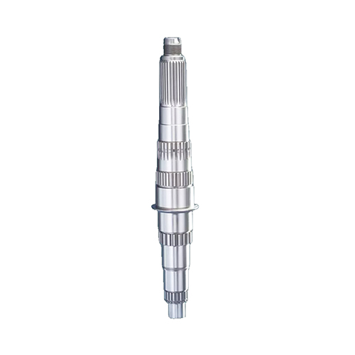
Shaft
A shaft is a rotating machine element that transmits power and torque from one location to another and supports rotating components such as gears, pulleys, sprockets and couplings. In powertrain systems, transmission shafts are subjected to combined torsion and bending from gear forces, chain or belt loads, and their own weight, so they must be designed for fatigue strength and stiffness over long service lives. DD Gear focuses on custom transmission shafts and gear shafts produced to customer drawings. These include input shafts, output shafts, gear shafts with integral gears, spline shafts and intermediate shafts used in EV drives, truck and off-highway gearboxes, industrial gearboxes, AGV drive units and automation equipment. Typical designs use forged alloy steels such as 42CrMo4 / AISI 4140 / SCM440 and related grades, which are widely used for heavily loaded shafts due to their strength and toughness. Shaft performance depends not only on material and heat treatment, but also on accurate bearing seats, fits and runout. DD Gear machines shaft journals, shoulders, splines and gear seats to tight tolerances based on ISO 286 fits for holes and shafts, helping customers achieve stable alignment, low vibration and long bearing and gear life. With small-module precision gearing capability inside the same plant, we can also supply integrated gear-shaft components, reducing assembly interfaces and improving concentricity.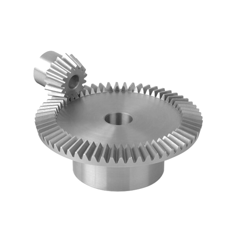
Bevel Gear
The Bevel Gear – Custom Bevel & Hypoid Gears for Angular Power Transmission is used to transmit motion and torque between intersecting or crossing shafts, typically arranged at a right angle. Bevel gears have teeth formed on the surface of a truncated cone, allowing power to “turn a corner” while maintaining a defined speed ratio. According to international standards such as ISO 23509, the term “bevel gears” includes straight bevel, spiral bevel, zerol bevel and hypoid gears. Straight bevel gears have straight teeth and are widely used where speeds and noise requirements are moderate, while spiral bevel gears use curved teeth to provide more gradual engagement, higher contact ratio and greater load capacity. Hypoid bevel gears, with offset axes, are commonly applied in automotive differentials and drive axles to handle high torque with smooth operation. DD Gear designs and manufactures custom bevel and hypoid gear sets based on customer drawings and specifications. Typical applications include automotive and EV differentials, steering systems, right-angle gearboxes for machinery, robotic joints and AGV drive axles, where compact angular transmission, efficiency and durability are essential. Geometry is designed in line with ISO 23509 and related bevel gear standards, while accuracy follows recognized systems such as DIN 3965 and the ISO bevel gear accuracy tables published via AGMA/ISO. With DD Gear’s focus on small-module precision gearing for emerging industries, we help customers build reliable angular drives with consistent contact patterns and long service lifePrecision Gears Built for the Future.
Trusted by Global OEMs, Proven in Every Application.
Your Custom Gear Solution Starts Here.


LOVE TO HEAR FROM YOU GET IN TOUCH!
Exploring The Science of Precision Gears

How to Select Carburized Case Depth for a Fine-Pitch Gear
A Fine-Pitch Gear needs a carburized case that supports the contact zone and tooth root while preserving a tough core. The drawing should define the depth by a recognized measurement method, identify the inspection location, and connect the requirement to material, heat treatment, finishing stock, and load. Module alone provides an initial scale; the final value follows a complete stress and process review. This guide explains the variables engineers should review before releasing a case-depth specification for compact metal gears used in robotics, electric drives, medical equipment, actuators, instruments, and automated machinery. Start with the case-depth definition Carburizing adds carbon to the steel surface. Quenching then forms a hard case around a lower-carbon core. The resulting hardness gradient affects surface fatigue, wear resistance, tooth-root strength, and resistance to subsurface damage. The term “case depth” needs a stated definition. Effective case depth is determined from a microhardness traverse to a specified limiting hardness. Total case depth is determined by the applicable measurement method defined in the relevant standard and represents the depth of the hardened case based on the specified criteria. Therefore, effective and total case depth values should not be treated as the same measurement. According to ISO 18203:2026, the depth of carburized and hardened cases in steel components is determined using specified measurement methods and evaluation criteria. A purchase drawing should define the applicable standard, case-depth type (effective or total), required depth range, limiting hardness where applicable, test method, inspection location, and acceptance criteria to ensure consistent interpretation between the heat treater and inspector. Scale case depth to the Fine-Pitch Gear tooth The tooth is the relevant section. A depth that is moderate on a large gear can occupy much of the root section on a small-module part. Engineers often begin with a case-depth-to-module relationship, then adjust it for stress, material, geometry, heat-treatment capability, and finishing operations. Research published by Gear Technology reports that the bending strength of case-carburized gears is influenced by the ratio of case depth to gear module. This relationship matters strongly in fine-pitch designs because the tooth tip, root fillet, and remaining core are small. Use the module ratio as a screening tool. A load-capacity calculation and metallurgical review should set the production range. ISO 6336-5:2016 covers material strength and quality considerations used in spur and helical gear load-capacity calculations, including requirements for case-carburized and hardened gears. Match depth to the governing failure mode Case-depth selection starts with the location and type of stress the gear must carry. Contact fatigue at the flank Hertzian contact stress creates a subsurface stress field below the active flank. The hardened zone should extend far enough to support that field under the specified torque, duty cycle, load distribution, and lubrication condition. A shallow hardened zone can place peak shear stress near softer material and increase the risk of case crushing, pitting, or deeper flank damage. Contact calculations should include dynamic load, face-load distribution, surface finish, profile modification, misalignment, temperature, lubricant viscosity, contamination, and expected life. A compact gear with intermittent shock loading may need a different hardness profile from a gear carrying smooth, steady torque. Tooth-root bending The root fillet carries cyclic tensile stress. The case at this location contributes hardness and compressive residual stress, while the core supports the tooth section. Root geometry, rim thickness, notch sensitivity, surface condition, and grinding marks all influence the required balance. A very deep high-carbon layer can reduce the proportion of tough core within a thin tooth. The engineering review should consider root bending strength together with the risk of excessive brittleness, quench cracking, and distortion. Wear, scuffing, and impact Wear and scuffing depend on surface hardness, roughness, sliding, lubricant film, temperature, and material pairing. Case depth supports the surface, while surface carbon, retained austenite, carbide distribution, and final finish affect how the flank behaves. Impact and overload place additional demand on core toughness. The specified steel and heat-treatment cycle should produce a hardness gradient that supports the case through the intended overload condition. Include the steel and core section Steel chemistry controls hardenability, carbon response, retained austenite, grain growth, and the hardness transition from case to core. Two gears with the same module and nominal depth can develop different profiles when they use different alloys or quench conditions. The Fine-Pitch Gear material review should cover: Steel grade and hardenability band Initial microstructure and incoming material condition Surface carbon target and carbon-potential control Carburizing temperature and diffusion schedule Quench method, agitation, and section size Tempering cycle and final surface hardness Core hardness and minimum supporting section Retained austenite, carbide network, and intergranular oxidation limits where required Thin rims, webs, hubs, keyways, and asymmetric features can change heating and cooling behavior. The gear blank design belongs in the case-depth review because the heat-treatment response follows the whole component. Account for grinding and stock removal The drawing should distinguish case depth before and after hard finishing. Gear grinding, gear-flank grinding, flank superfinishing, or other stock-removal operations reduce the finished case. The process route needs enough allowance to achieve the specified depth on the final surface. Grinding also adds thermal and mechanical risk. Excess heat can temper the surface, create tensile residual stress, or produce grinding cracks. Inspection may therefore include surface hardness, microhardness profile, nital etch or another burn-detection method, tooth geometry, and crack detection according to the drawing and application. For a Fine-Pitch Gear, small stock changes represent a larger fraction of the tooth. Heat-treatment distortion can also shift profile, lead, runout, and tooth thickness. The manufacturing plan should link pre-heat geometry, expected growth or shrinkage, grinding stock, and the finished case-depth requirement. Specify where the case depth is measured Carburizing response varies around the tooth. The tip, pitch-line region, root fillet, end face, and masked surfaces can show different carbon diffusion and cooling conditions. A requirement that lists only one depth range leaves the inspection location open to interpretation. Define the location on a Fine-Pitch Gear drawing or inspection plan. Useful details include: Tooth flank, root, or both Distance from the tip, pitch line, or root tangent Mid-face position or a defined distance from the end face Test direction and surface normal Number of samples and sampling frequency Production gear, sacrificial gear, or representative coupon Effective-depth limit hardness and traverse spacing Acceptance rules for surface hardness, core hardness, and microstructure A coupon can confirm furnace conditions and material response. A sectioned gear captures local tooth geometry, section thickness, stock removal, and quench response. Critical programs may use both forms of evidence. Use a drawing-based selection workflow The following sequence keeps the design calculation, heat-treatment route, and inspection record aligned. Review step Engineering input Required output 1. Define duty Torque spectrum, speed, life, overload, temperature, lubrication Design load cases and safety factors 2. Calculate gear stresses Module, tooth count, pressure angle, helix angle, face width, modifications Contact and root stress results 3. Select material Steel grade, hardenability, core section, blank condition Material and core-hardness requirements 4. Set the case range Stress depth, module ratio, root support, process capability Preliminary effective case-depth range 5. Add process allowances Distortion, grinding stock, finishing sequence Pre-finish and finished depth targets 6. Define verification Standard, test location, hardness threshold, sampling Inspection plan and report fields 7. Validate production First article, hardness profile, microstructure, gear geometry Approved process window This workflow produces a traceable specification. Each depth value connects to a stress calculation, material response, manufacturing operation, or inspection result. Common specification errors Using module as the only input Module provides geometric scale. Torque, tooth count, face width, load distribution, service life, steel, core section, and finishing route determine how the case supports the design. Listing depth without a hardness criterion Effective and total case depth use different evaluation criteria. State the applicable measurement standard, case-depth definition, and limiting hardness where required so that test reports describe the same property. Ignoring the root location A flank measurement supports contact-fatigue review. Root bending may require a separate depth and microstructure check at the fillet. Applying the pre-grind result to the finished gear Hard finishing removes material and may alter surface condition. The final acceptance plan should address the finished tooth when the drawing controls delivered performance. Treating the furnace coupon as the complete result Coupons provide useful process evidence. Local tooth geometry and section size affect the production part, so the validation plan should include representative gear sections where risk or customer requirements justify them. DD Gear support for case-depth planning DD Gear produces custom high-precision gears for robotics, EV, AGV, medical equipment, electric tools, and industrial automation projects. Its process planning can connect drawing review, blank preparation, tooth cutting, heat treatment, hard finishing, and final inspection. The company’s quality-assurance process covers incoming material checks, in-process inspection, gear measurement, CMM inspection, surface-roughness analysis, and traceability. For a carburized gear project, the inspection scope can add the hardness traverse, effective case depth, core hardness, microstructure, retained austenite, and crack-detection records required by the drawing. Send the gear drawing, material specification, module, tooth data, load spectrum, heat-treatment requirement, finishing stock, annual quantity, and inspection-document list. DD Gear can review a Fine-Pitch Gear project against its custom gear manufacturing capabilities and prepare a process route for technical discussion. Conclusion Case depth for a Fine-Pitch Gear follows the tooth scale, stress field, failure mode, steel response, core section, heat-treatment process, and finishing allowance. The drawing should state the depth definition, measurement standard, hardness threshold, test location, sampling plan, and finished-part acceptance range. A first-article hardness profile and metallurgical review provide evidence for the selected process window. Share the project data through the DD Gear contact page to review the carburizing, finishing, and inspection route. FAQ What is effective case depth in a carburized gear? Effective case depth is the perpendicular distance from the surface to the point where hardness reaches a specified limiting value. The drawing should identify the governing standard (such as ISO 18203:2026), hardness threshold, test method, and measurement location. Does a smaller module always require a shallower case? Smaller teeth generally use a shallower absolute case because the tooth section is smaller. The final requirement also follows contact stress, root stress, material, core support, life, overload, and finishing stock. Should case depth be checked at the flank or root? The inspection location should match the controlled risk. Flank measurements support contact-fatigue evaluation, while root measurements support bending and fillet assessment. Some projects specify both. How does gear grinding affect case depth? Grinding removes part of the carburized layer. The heat-treatment target should include grinding allowance, and the finished gear should retain the depth and hardness profile stated on the drawing. What data should a supplier receive before quoting carburizing? Provide the drawing revision, module, tooth geometry, steel grade, load and life targets, surface and core hardness, case-depth definition (effective or total), applicable heat-treatment standard (such as ISO 18203:2026), finishing stock, inspection location, sampling plan, and required records.

What Determines the Price of Custom Precision Gears
The Price of Custom Precision Gears comes from the complete manufacturing and verification plan. Geometry, material, machining route, heat treatment, accuracy, quantity, inspection, tooling, and delivery each add defined work to the quotation. For procurement teams, the useful question is how each requirement changes setup time, cycle time, process risk, inspection hours, and batch yield. A complete RFQ gives suppliers a consistent basis for quoting prototypes and production orders. The main price drivers Custom Precision Gears are priced from these connected inputs: Gear type, size, tooth geometry, and integrated features Material grade, blank form, and availability Machining, tooth cutting, heat treatment, grinding, and finishing Accuracy grade, dimensional tolerances, and surface finish Prototype, annual, and release quantities Tooling, fixtures, programming, and first-article work Inspection reports, certificates, traceability, and sampling Packaging, schedule, Incoterms, and destination Procurement teams should compare the included process route, one-time charges, documents, quantity basis, delivery terms, and technical exceptions. These fields explain why two unit prices may represent different supply packages. One-time costs and recurring unit cost One-time engineering expenses can include drawing review, process planning, programming, cutting tools, fixtures, gauges, heat-treatment trials, and first-article inspection. These items establish the manufacturing route and may support later releases when the design remains unchanged. Recurring unit cost covers material, machine time, heat treatment, finishing, inspection, packaging, and production overhead. Setup work is distributed across the batch, so the same part can carry different unit prices at 5, 50, 500, and 5,000 pieces. Ask each supplier to identify tooling ownership, expected tooling life, storage terms, replacement responsibility, and the conditions that require a new setup or validation charge. Geometry and manufacturing route External spur gears often allow a direct hobbing route. Helical gears add helix control. Internal gears may require shaping, broaching, skiving, or wire EDM. Bevel, worm, face, and double-helical gears use distinct tooling and machine platforms. Integrated shafts, thin rims, deep shoulders, splines, keyways, cross holes, and restricted cutter access add operations or special workholding. The RFQ should define tooth count, module or diametral pitch, pressure angle, helix angle, face width, profile modifications, and datum relationships. A process-route summary helps buyers compare offers. Typical operations include blank preparation, CNC turning, tooth cutting, deburring, heat treatment, bore finishing, gear grinding, cleaning, and final inspection. Material, heat treatment, and finishing Material affects raw cost, machinability, hardenability, distortion, certification, and lead time. Common blank forms include bar, tube, casting, forging, and near-net preforms. Bar stock often supports flexible prototype work, while a production forging can add tooling and reduce machining stock for a suitable application. Carburizing, nitriding, induction hardening, through hardening, and quench-and-temper routes require different cycles and tests. Surface hardness, core hardness, case depth, microstructure, retained austenite, and crack inspection can expand the process and reporting scope. Heat treatment may change bore size, tooth profile, lead, and runout. Tight finished geometry can require stock allowance and grinding after treatment. State the material standard, permitted equivalents, heat-treatment method, hardness, case-depth definition, coating, and required certificates before quotation. Accuracy and dimensional tolerances Accuracy requirements control machine selection, finishing, inspection time, and expected yield. Gear profile, lead, pitch, runout, and tooth thickness need suitable measurement equipment. ISO 1328-1:2013 establishes a system for classifying the flank tolerance of cylindrical involute gears. The drawing should name the standard, edition, grade, controlled characteristics, and measurement conditions. Bore size, face runout, concentricity, perpendicularity, shoulder position, and surface finish can also require grinding or dedicated fixtures. Apply each tolerance according to assembly, load distribution, noise, and service-life requirements. Quantity and delivery schedule Prototype quantities carry engineering, setup, and inspection across a small number of parts. Production quantities distribute that work and may support dedicated cutters, multi-part fixtures, automation, or forging dies. Provide separate figures for prototypes, pilot builds, annual demand, and normal release size. Suppliers can then quote quantity breaks using consistent technical assumptions. Lead time includes material procurement, tooling, machine scheduling, heat treatment, inspection, and customer approval. A compressed schedule may require priority material, overtime, split batches, or premium freight. Packaging, rust prevention, export cartons, cleanliness, Incoterms, and destination charges also belong in the commercial comparison. Inspection and documentation Inspection cost reflects measurement time, equipment, sampling, report preparation, laboratory tests, and record retention. Required documents may include: Material and heat-treatment certificates First Article Inspection Report or PPAP package Gear profile, lead, pitch, and runout report CMM report for bore, faces, datums, and integrated features Hardness, case depth, microstructure, or crack-detection records Batch, material-lot, and process traceability DD Gear’s quality-assurance process covers incoming material checks, in-process inspection, gear measurement, CMM inspection, surface-roughness analysis, and traceability. Buyers should define the required records and sampling level in the RFQ. Quotation comparison table Use the same fields when comparing the Price of Custom Precision Gears from several suppliers. Quotation field Confirm in each offer Procurement purpose Technical basis Drawing revision and approved deviations Aligns every price with one design Process route Blank, tooth cutting, heat treatment, finishing Identifies differences in scope One-time charges Engineering, tooling, fixtures, validation Separates investment from unit price Unit-price basis Quantity, batch size, currency Supports comparable quantity breaks Inspection Characteristics, sampling, reports Aligns quality evidence Delivery Lead time, packaging, Incoterm, destination Supports landed-cost comparison Commercial terms Validity, surcharge basis, payment terms Records exposure to later changes This table turns a quoted number into a defined supply package shared by procurement, engineering, and quality teams. RFQ checklist for Custom Precision Gears Send these items for a quotation based on a complete scope: Matching 2D drawing and 3D model revisions Gear type, module or DP, tooth count, pressure angle, helix angle, and face width Material, blank preference, heat treatment, hardness, and coating Accuracy standard, grade, datums, tolerances, and surface finish Prototype quantity, annual demand, and release size Application, torque, speed, life, lubrication, and environment Certificates, gear reports, CMM data, FAI, PPAP, and traceability Packaging, destination, Incoterm, and required date For replacement gears, include the sample condition, mating-part data, photographs, operating history, and known failure mode. Reverse engineering adds measurement and design-confirmation work to the quotation. How DD Gear prepares a quotation DD Gear supports custom metal gears for robotics, EVs, AGVs, medical equipment, electric tools, and industrial automation. Its manufacturing capability overview covers OEM and ODM support, cooperation planning, quality assurance, and technical support. The quotation review considers the drawing, application, material, accuracy, quantity, heat treatment, finishing route, and inspection package. The offer can separate engineering or tooling charges, sample pricing, quantity-based production pricing, documents, lead time, and delivery terms. DD Gear’s cooperation process connects requirement review, technical consultation, quotation, sample development, production, and delivery. Share the RFQ through the contact page for a manufacturing and commercial review. Conclusion The Price of Custom Precision Gears reflects the work required to manufacture, finish, inspect, document, package, and deliver the specified part. Geometry and accuracy define machine capability. Material and heat treatment define process response. Quantity distributes setup and tooling costs. A revision-controlled RFQ gives suppliers a consistent quotation basis and gives buyers a practical comparison across process scope, unit price, quality records, and delivery terms. FAQ Why do prototype gears have a higher unit price? Prototype prices distribute engineering, programming, setup, inspection, and validation across a small number of pieces. Production batches distribute these activities across more parts. Does a higher accuracy grade increase price? A tighter accuracy requirement can add controlled machining, grinding, process checks, measurement time, and yield risk. The effect depends on geometry, material, and heat treatment. What changes the Price of Custom Precision Gears after quotation? Drawing revisions, quantity changes, material substitutions, added heat treatment, tighter tolerances, expanded inspection, revised packaging, and expedited delivery can change the commercial basis. What should buyers compare besides unit price? Compare the drawing revision, manufacturing route, tooling charges, quantity basis, inspection package, certificates, lead time, delivery terms, exclusions, payment terms, and quotation validity.
CNC Machining vs Hobbing for Prototype Gears: Guide
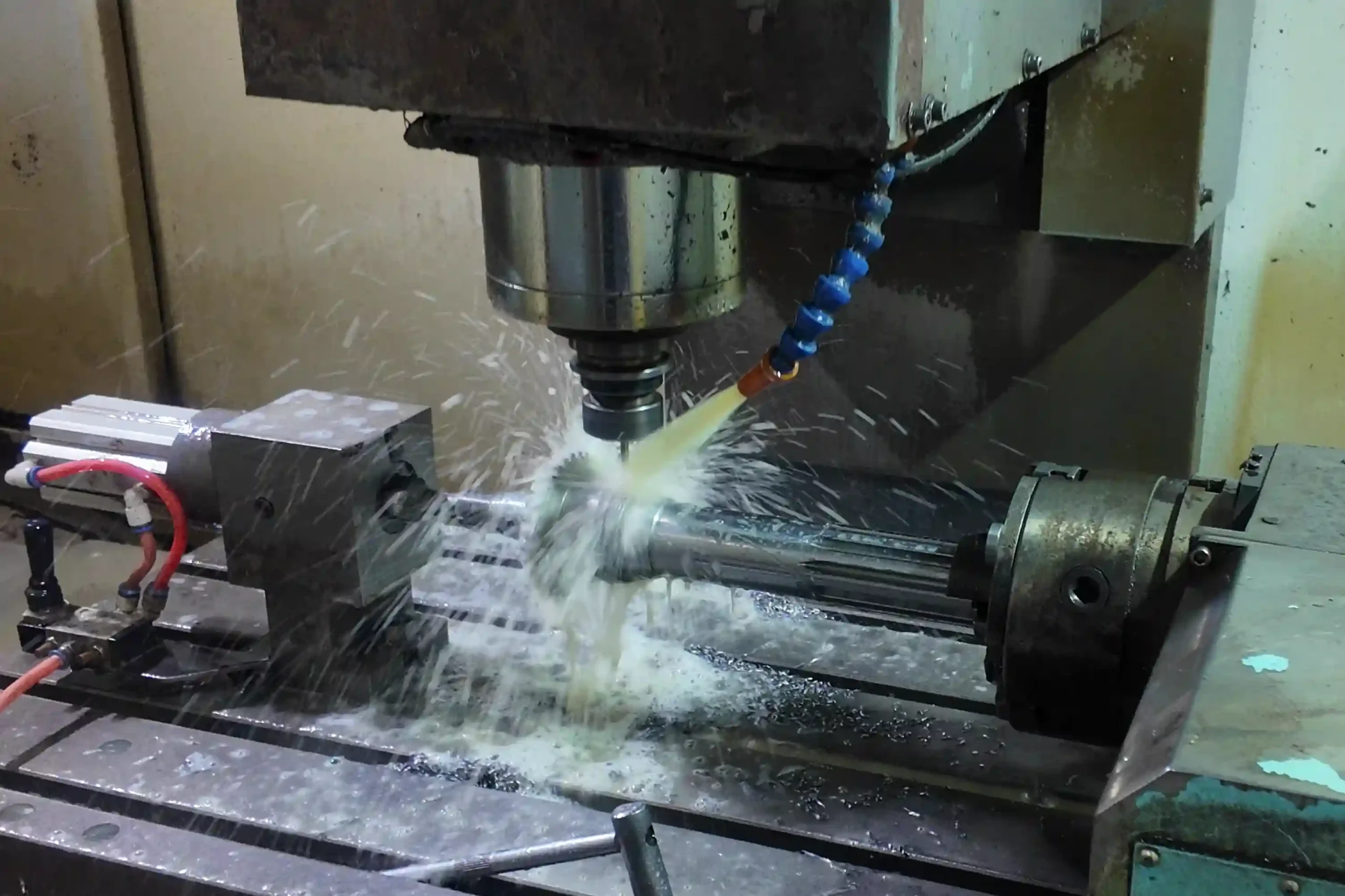
Prototype Gears need a process that fits the design stage, the tooth geometry, and the expected production path. CNC machining can produce a one-off gear with flexible tool access. Hobbing uses a generating cutter to form external spur or helical teeth with a repeatable motion. The better choice depends on the gear drawing, quantity, module, material, accuracy target, and the next build stage. For a small-module metal gear used in robotics, an EV drive, an AGV, medical equipment, or automated machinery, process selection should start with the drawing. A prototype that will move into a pilot batch may need a different route from a single geometry study. CNC machining often suits a single prototype, an unusual tooth form, an internal gear, or a design that will change during testing. It can combine turning, milling, drilling, and other operations in one flexible setup. The programmer can adjust the tool path as the drawing develops. Hobbing often suits external spur and helical gears when the tooth form is defined and the project needs repeatable parts. The hob and workpiece rotate in a controlled ratio, so the cutter generates the tooth spaces continuously. A hobbing route also gives the engineering team a clearer bridge to later batch production. The comparison needs one technical correction: hobbing machines can use CNC control. CNC machining describes a control and manufacturing platform. Hobbing describes a gear-tooth cutting method. A CNC gear hobbing machine belongs to both categories. What CNC machining means in a gear project CNC machining covers programmed material removal with turning centers, machining centers, gear shaping equipment, and other CNC machines. In a prototype gear route, CNC turning can prepare the bore, outside diameter, faces, shoulders, and datums. Milling can produce selected tooth forms, slots, keyways, or custom features. For a simple spur or helical gear, CNC milling may cut one tooth space at a time with a form tool or end mill. This method can support single-piece work and large or unusual geometries. It also requires careful control of indexing, tool condition, workholding, and final tooth inspection. CNC machining has value when the design is still moving. A team can update the program after a drawing change, test a new bore or shoulder, and keep the prototype route connected to the same machining logic. The final tooth accuracy still depends on machine capability, tool geometry, setup, material, and inspection method. What hobbing adds to Prototype Gears Hobbing follows the meshing principle of a worm gear pair. A multi-edge hob rotates while the gear blank rotates at a defined ratio. Axial feed moves the cutter across the tooth width, and radial feed controls the cutting depth. The continuous cutting motion gives hobbing a practical advantage for repeated external teeth. The same hob, setup logic, and inspection plan can support several parts after the design is confirmed. The process is commonly used for spur gears, helical gears, small-module gears, and selected splined forms. Hobbing also has boundaries. Standard hobbing does not cover every internal gear geometry. Tool selection depends on module, pressure angle, helix angle, tooth count, face width, material, and machine envelope. A special hob adds cost and preparation time, so the project should compare that investment with the required quantity and future batch plan. CNC machining vs hobbing: a practical comparison Decision factor CNC machining Hobbing Typical use One-off parts, unusual geometry, internal gears External spur or helical gears with a defined tooth form Tooling General or project-specific cutting tools Hob matched to gear geometry Tooth cutting Discrete tooth-space cutting or programmed milling Continuous generating motion Design changes Program changes can be applied quickly Changes may affect hob selection and setup Repeated parts Useful when the same setup remains stable Strong fit for repeatable external teeth Prototype-to-production path Depends on the later process choice Can carry process logic into pilot batches The table describes process tendencies. A drawing review determines the feasible route for a specific gear. Which process is better for a first prototype? Choose CNC machining when the design is still changing CNC machining is a sensible starting point when the engineering team is testing bore size, tooth count, face width, mounting features, or a custom profile. The process gives the programmer room to adjust features before a dedicated hob is approved. It also fits internal gears and parts with shoulders that limit cutter access. For very large modules or one-off parts, milling may be easier to plan than a dedicated generating process. The inspection plan should include tooth profile, pitch, runout, and the drawing dimensions that control assembly. Choose hobbing when the tooth form is stable Hobbing becomes more attractive when the external tooth geometry is approved, the material and heat-treatment route are defined, and the project expects more than one prototype or a pilot batch. The process can provide a consistent cutting relationship across the tooth set. Hobbing can also reduce the gap between prototype and production planning. The same gear type, cutter logic, datum scheme, and inspection characteristics can be reviewed during the next build. The supplier should still confirm the module range, machine capability, tool availability, and post-heat-treatment finishing plan. Use a combined route when the gear needs it Many metal gears use several processes in sequence. A forged blank can support material structure and strength requirements. CNC turning can establish the bore and reference surfaces. Hobbing can cut external teeth. Heat treatment can set the required material condition, and grinding can correct tooth geometry after treatment when the drawing requires it. This route gives CNC machining and hobbing different jobs. One process prepares the blank and datums; the other generates the teeth. The complete process plan assigns each machine to the operation it controls. What to confirm before selecting a process Send the supplier the information that changes tool selection and inspection scope: Gear type: external, internal, spur, helical, bevel, worm, or planetary Module, number of teeth, pressure angle, helix angle, and face width Bore, keyway, spline, shoulder, and datum requirements Material grade, blank route, heat treatment, and surface finishing Quantity for prototypes, pilot builds, and expected production Accuracy standard, inspection documents, and acceptance criteria Load, speed, duty cycle, lubricant, and application environment The supplier should return a process route that names the blank preparation, tooth-cutting method, finishing steps, inspection points, and items that require drawing confirmation. DD Gear’s custom gear manufacturing capability can be reviewed alongside these project inputs. How DD Gear approaches custom Prototype Gears DD Gear focuses on custom small-module high-precision metal gears for robotics, EVs, AGVs, medical equipment, electric tools, and automated machinery. The company works from customer drawings, design requirements, or physical samples. The route can include forging, CNC machining, hobbing, shaping, heat treatment, grinding, and finished-product inspection according to the project. The knowledge base identifies dimensions, hardness, and runout as finished-product inspection items. A project may also require tooth profile, lead, pitch, material traceability, case depth, or contact checks. The final inspection scope follows the drawing revision, accuracy target, material, gear type, application, and agreed documentation. PairGears, DD Gear’s parent company, describes inspection equipment for dimensional measurement, material verification, CMM checks, and tooth profile, helix, pitch, and runout reports in its manufacturing and inspection equipment overview. For cylindrical gear accuracy, the project can reference ISO 1328-1:2013 or another standard named on the drawing. For a technical review, provide the drawing revision, gear type, module, tooth data, material, heat-treatment requirement, quantity, application conditions, and required inspection records. DD Gear can then confirm whether CNC machining, hobbing, or a combined route fits the prototype stage. Conclusion CNC machining is often a good fit for a one-off prototype, a changing design, an internal gear, or an unusual geometry. Hobbing is often a good fit for stable external spur and helical teeth, repeated prototypes, and pilot production. A CNC hobbing machine can use both CNC control and the hobbing method. The decision should follow the drawing, quantity, module, material, accuracy target, tooling plan, and next build stage. A combined route may use forging, CNC datum work, hobbing, heat treatment, and grinding. Share the project details through the DD Gear contact page to review the process route and inspection documents. FAQ Q1: Is CNC machining better than hobbing for Prototype Gears? A: CNC machining suits changing designs, one-off parts, internal gears, and unusual geometries. Hobbing suits stable external spur or helical teeth and repeated parts. The drawing and project quantity determine the practical choice. Q2: Can hobbing be used for a single prototype gear? A: Yes, when the external tooth form is stable and the tooling plan fits the project. The supplier should confirm hob availability, setup time, module, material, and the expected follow-up quantity. Q3: Is hobbing a CNC machining process? A: Hobbing is a tooth-cutting method, while CNC describes programmed machine control. A CNC gear hobbing machine uses both concepts in one process. Q4: Can CNC milling make a helical prototype gear? A: CNC milling can produce selected helical geometries when the machine, tool path, workholding, and inspection method support the design. The supplier should validate tooth profile, lead, pitch, and runout against the drawing. Q5: What information does a prototype gear supplier need? A: Provide the drawing revision, gear type, module, teeth, pressure angle, helix angle, bore and datum details, material, heat treatment, quantity, application load, speed, and required inspection documents.
What Should a Gear Inspection Report Include?
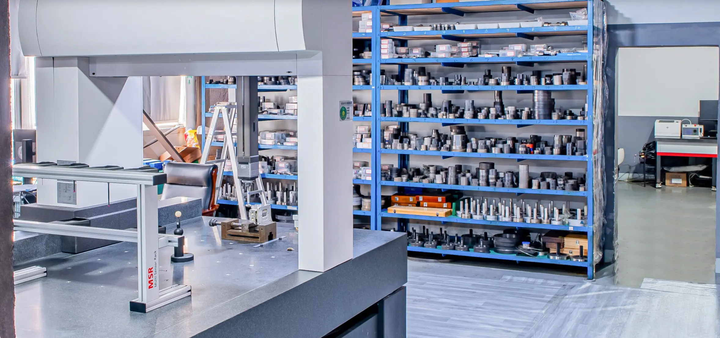
A Gear Inspection Report should connect the customer drawing to measured evidence. A useful report identifies the part and revision, records material and batch data, lists critical dimensions, shows tooth geometry results, documents heat treatment where required, and states the acceptance basis. The exact scope follows the gear type, drawing, accuracy target, material, application, and agreed inspection plan. For a custom metal gear used in robotics, an EV drive, an AGV, medical equipment, or another automated system, the report supports a release decision. It gives engineering, quality, and purchasing teams a shared record for fit, tooth contact, material condition, and process traceability. What Is a Gear Inspection Report? A Gear Inspection Report is a controlled record of measurements and checks performed on a defined gear or gear lot. It should show the nominal value, tolerance, actual result, measurement method, and status for each characteristic that matters to the drawing or application. The report works with the latest drawing revision and the agreed quality plan. Each result needs a clear datum, tolerance, method, and part identity. Core Identification and Traceability Data Part and Drawing Information The first section should identify the inspected part quickly. Include: Part number and drawing number Drawing revision and customer purchase reference Gear type, such as spur, helical, bevel, worm, internal, or planetary gear Number of parts inspected and inspection date Inspector, reviewer, report number, and sampling status This information ties the measurement record to the correct design revision. Material and Batch Traceability Material records should identify the specified grade and heat or batch number. A material certificate can add chemical composition and supplier reference. Connect that record to the inspected parts. When specified, heat-treatment records can reference the process batch, treatment route, hardness target, and follow-up checks. Dimensional Inspection Results Critical Gear Dimensions A dimensional inspection report should list features that control assembly and alignment. Depending on the drawing, these may include: Report area Typical data to record Engineering purpose Functional dimensions Bore, outside diameter, face width, tooth thickness Fit and torque transfer Mounting features Keyway, spline, bolt pattern, shoulder, datum surfaces Positioning and assembly Geometric relations Concentricity, perpendicularity, parallelism, runout Alignment and rotational stability Surface condition Roughness or edge condition when specified Contact and assembly Show the nominal, tolerance, measured value, and instrument or method. CMM, vision measurement, bore gauges, or other systems may be selected by feature and inspection requirement. Measurement Method and Acceptance Basis Each result needs a datum reference, measurement unit, and acceptance basis. Record fixturing or environmental conditions when they affect the result. Tooth Geometry and Gear Accuracy Tooth Profile and Lead or Helix A gear tooth profile inspection report compares the measured flank with the design profile. It records profile deviation, total profile error, and the tolerance band. Repeated results near one limit can indicate process movement. Lead or helix results show tooth direction across the face width. Identify lead deviation, helix deviation, measurement direction, and permitted range. Both profile and lead charts matter when contact position is controlled. Pitch, Runout, and Tooth Spacing Pitch inspection covers tooth spacing. The report may include single pitch deviation, cumulative pitch deviation, and tooth-to-tooth variation. Radial runout connects the tooth set to the inspection datum. State the datum, runout value, measurement direction, and tolerance. Accuracy Standards Name the accuracy standard and grade used for evaluation. ISO 1328-1:2013 defines a tolerance classification system for individual cylindrical involute gear flanks. AGMA, DIN, JIS, or a customer-specific system may apply. List the selected standard, edition, gear type, and grade. Material, Heat Treatment, and Surface Condition Hardness records should identify the test location and method. Depending on the design, the report may separate surface and core hardness. A carburized or nitrided gear may require case depth, metallography, or a process certificate. Surface treatment data should match the material and drawing requirement. Include treatment batch, process date, hardness, case depth, and post-treatment finishing when specified. Noise, backlash, and lost-motion results require system conditions. Describe the test setup, load, speed, lubricant, mating gear, and acceptance limit when specified. Use performance terms only when the drawing and validated method define them. Application-Specific Checks The inspection plan should follow the gear geometry and operating role. A matched bevel pair may require contact pattern, backlash, and tooth thickness checks. A small helical gear for an EV or robot joint may require profile, lead, pitch, runout, hardness, and case-depth records. An AGV drive gear may add bore and shaft-fit checks. Application Checks that may be specified Information to confirm Robotics and joint drives Profile, lead, pitch, runout, backlash Motion and load conditions EV drive systems Tooth geometry, hardness, case depth, NVH test Speed, torque, test setup AGV and automation Dimensions, runout, tooth thickness, material Duty cycle and datum Medical equipment Dimensions, surface condition, traceability Cleanliness and load The table is a planning guide. The final report scope follows the approved drawing and project control plan. How to Review a Gear Inspection Report Before Approval Use this sequence during supplier review: Match the report to the latest drawing revision and part number. Confirm every nominal value, tolerance, unit, and actual measurement. Check the datum and measurement method for each critical feature. Review profile, lead, pitch, and runout charts with their tolerance bands. Verify material, heat-treatment, hardness, and case-depth traceability when specified. Ask the supplier to explain missing data or an out-of-limit result. Record the final disposition and any follow-up action. For custom projects, you can compare the requested evidence with the supplier’s custom gear manufacturing capability. The inspection method should follow the actual feature and drawing requirement. Conclusion: Use the Report to Make a Release Decision DD Gear’s Inspection Documentation DD Gear focuses on custom small-module high-precision metal gears for robotics, EVs, AGVs, medical equipment, electric tools, and automated machinery. Customers provide drawings, design requirements, or physical samples. DD Gear reviews the design and follows a route that can include machining, heat treatment, finishing, and final inspection. The knowledge base identifies hardness, dimensions, and runout as finished-product inspection items. The report scope remains project-specific and follows the drawing, material, accuracy target, gear type, application, and documentation request. PairGears, DD Gear’s parent company, presents equipment and report examples for dimensional measurement, material verification, CMM inspection, and gear geometry checks in its manufacturing and inspection equipment overview. When requesting a review from DD Gear, provide the drawing revision, material, module, tooth data, load, speed range, application, quantity, and required inspection documents. Release Decision A useful Gear Inspection Report links the drawing, inspected parts, measurement method, and release decision. It usually covers identification, dimensions, tooth geometry, accuracy standard, material, heat treatment, and application-specific checks. Each result should include its nominal value, tolerance, actual value, datum, and test basis. DD Gear supplies custom small-module metal gears for robotics, EVs, AGVs, and automation. For a technical review, send the drawing revision, material, gear type, application conditions, quantity, and required evidence through the custom gear project contact page. FAQ Q1: What should a Gear Inspection Report include? A: It should identify the part and drawing revision, record material and batch traceability, list critical dimensions, show tooth profile, lead, pitch and runout results where required, and document hardness or heat-treatment checks specified by the project. Q2: What is checked in a gear tooth profile inspection report? A: The report compares the measured tooth flank with the design profile and records profile deviation, total profile error, measurement conditions, and the applicable tolerance band. The chart should identify the gear, datum, measurement direction, and standard used for evaluation. Q3: Does every gear project require an ISO 1328 inspection? A: ISO 1328 applies to the cylindrical involute gear characteristics covered by the selected edition and scope. The drawing or quality plan should confirm whether ISO 1328, AGMA, DIN, JIS, or a customer-specific standard governs the project. Q4: What is the difference between a dimensional report and a gear accuracy report? A: A dimensional report records features such as bore, outside diameter, face width, keyway, and datum relationships. A gear accuracy report focuses on tooth profile, lead or helix, pitch, runout, and related gear deviations. Q5: Which inspection documents should you request from a custom gear supplier? A: Request the dimensional report, gear geometry report, material certificate, heat-treatment or hardness record, and any case-depth, contact-pattern, or functional test record named in the drawing. Confirm the sampling basis and the report format before production.
Driving Precision Forward with
Custom gear solutions
Please fill out the form below and we will get back to you as soon as possible.